background image

Form No. Z2025A

Rev. 12.05.03

INSTALLATION AND OPERATION INSTRUCTIONS

DIRECT DRAW DISPENSER - SELF-CONTAINED MODELS

Table of Contents

PREPARING THE CABINET FOR USE
Specifications.........................................................2
List of Included Parts.............................................3
Tools Required.......................................................3
Plumbing................................................................3
Electrical ................................................................3
Installing Casters or Legs......................................3
Installing Faucet and Standard..............................3
TAPPING
Connecting the Keg Coupler .................................4
Tapping the Keg.....................................................4
Connecting the Regulator......................................5
Adjusting Gas Flow................................................5
CO

2

Leak Test .......................................................5

Replacing a CO

2

Gas Cylinder..............................5

Handling CO

2

Gas .................................................5

TEMPERATURE
Beer Temperature ..................................................6
Refrigeration and Temperature Control .................6
CLEANING
Cleaning the Beer Lines ........................................7
Cleaning the Cabinet .............................................7
GENERAL INFORMATION
How to Pour a Perfect Glass of Beer ....................8
Troubleshooting .....................................................9
Beer Facts .............................................................9
REPLACEMENT PARTS ................................10-11
Wiring Diagram ....................................................12

8300 West Good Hope Road  •  Milwaukee, WI 53223  •  Phone 414-353-7060  •  Fax 414-353-7069

Toll Free 800-558-5592  •  E-Mail: [email protected]  •  www.Perlick.com

MODEL NOS.

DS Series

IMPORTANT INFORMATION

Fill out the enclosed warranty card and mail to the
Perlick Corporation to register the warranty. If the
card is not returned, the warranty period will begin
from the date the equipment is shipped from the 
factory.

This manual has been prepared to assist you in the
installation of your Direct Draw Dispenser and to
acquaint you with its operation and maintenance.

We dedicate considerable time to ensure that our
products provide the highest level of customer 
satisfaction. If service is required, your dealer can
provide you with a list of qualified service agents. For
your own protection, never return merchandise for
credit without our approval.

We thank you for selecting a Perlick product and
assure you of our continuing interest in your
satisfaction.

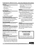
WARNING: When lifting, the full weight of the
cabinet must be supported. Lift from the cabinet
base and not from the top. Improper lifting can
result in severe damage to the cabinet.

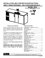
Summary of Contents for DS Series

Page 1: ...800 558 5592 E Mail Perlick Perlick com www Perlick com MODEL NOS DS Series IMPORTANT INFORMATION Fill out the enclosed warranty card and mail to the Perlick Corporation to register the warranty If the card is not returned the warranty period will begin from the date the equipment is shipped from the factory This manual has been prepared to assist you in the installation of your Direct Draw Dispen...

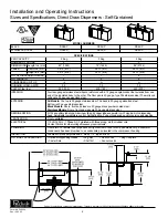
Page 2: ... 134a capillary tube type Aluminum fin and copper tube evaporator coil Forced air into dispensing head Adjustable temperature control Self defrosting Pull out condensing unit for service and cleaning VENTILATION Front ventilated ELECTRICAL 115 Volt 60 Hz 1 Phase AC Furnished with three prong six foot rubber cord Contact Perlick for other voltage frequency requirements PLUMBING Floor drain 3 4 fema...

Page 3: ...he dispensing head to seal it to the top Align the dispensing head over the holes on the cabinet top and use screws provided to secure standard to cabinet top Wipe off excess RTV to complete the seal Attach faucet to standard using spanner wrench to tighten coupling Attach faucet handle to faucet Insert flexible plastic air hose six to seven inches into bottom of faucet standard Secure hose with t...

Page 4: ...ut end of black beer line connector hose and thread onto top of keg coupler Hand tighten Place clamp on one end of red air line Push end over air valve located inside cabinet Tighten clamp with screwdriver Turn shut off valve to OFF horizontal position Place clamp on the other end of red air line and push over tailpiece on coupler Tighten clamp with screwdriver CAUTION Do not use keg coupler as a ...

Page 5: ...alve counterclockwise until fully open Turn regulator shut off valve to open position Adjust CO2 gas flow as required turning clockwise for higher pressure Proper CO2 Handling ALWAYS Connect a regulator reducing valve to CO2 cylinder Secure cylinder in upright position whether in storage or in use Keep cylinder away from heat Rupture disc vents at 122 F maximum Ventilate room after high pressure g...

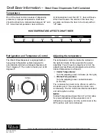
Page 6: ...igned to automatically maintain a storage temperature of 36 41 degrees F The control is factory set at 38 degrees F Adjusting the temperature The temperature control is inside the cabinet on the right hand side of the evaporator fan panel assembly You will need a screwdriver to turn the adjusting screw Make small adjustments until the desired temperature is achieved Colder Temperatures Turn the ad...

Page 7: ...indicate bacterial growth Yeast All domestic draft beers contain a small amount of yeast which remains in the beer from the fermentation process When the temperature of draft beer exceeds 50 a process of secondary fermentation may take place The beer faucet may exhibit a white colored substance yeast build up if not cleaned on a regular basis Beer Stone All beer contains calcium which is present f...

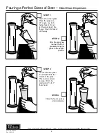
Page 8: ... a clean glass Place the glass at a 45 angle one inch below faucet Do not let the glass touch the faucet Open the faucet all the way STEP 1 Let the remaining beer run straight down the middle of the glass This ensures proper release of CO2 by producing a 3 4 to 1 foam head STEP 3 After the glass has reached half full gradually bring the glass to the upright position STEP 2 Close the faucet quickly...

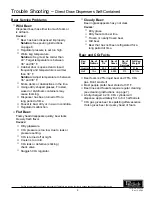
Page 9: ...ressure is too low due to leak or pressure setting CO2 is turned off at night Cooler is too cold CO2 leak or defective sticking check valve Sluggish CO2 regulator Cloudy Beer Beer in glass appears hazy not clear CAUSES Dirty glass Dirty faucet or beer line Frozen or nearly frozen beer Old beer Beer that has not been refrigerated for a long period of time Beer and CO2 Facts Keg No of No of No of No...

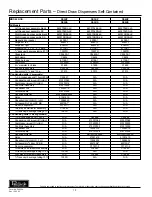
Page 10: ...2019 N A N A Terminal board 219101538 N A N A Overload protector MRT20AGK5590 N A N A Relay 21351619 N A N A Capacitor 282 339 MFD 155V 13556529 N A N A Coil assembly 2 door SC BB 62210A1 N A N A Fin coil evaporator C17511 1 N A N A Two way air distributor assembly C18942 N A N A 1 2 trans vinyl beverage tubing 9 ft 1390R N A N A Condensing units 3 4 keg models 1 3 h p condensing unit 115 volt N A...

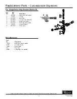
Page 11: ...ler Series D Item Part No No Description 1 26000D Single valve keg coupler 2 C14316 O ring 3 31080 2P Ball check 4 31089 2P O ring 3 per assembly 5 31088 2P Bottom seal washer 6 31087 2P Probe washer domestic 7 157R2P Coupling Gasket 8 23682 2P Check valve Miscellaneous Part No Description 157L2P Beer line connector gasket 57F2P CO2 tank washer 1392R Red air hose 529 Beer hose 2928D Twin gauge CO2...

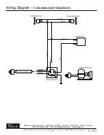
Page 12: ...3 Phone 414 353 7060 Fax 414 353 7069 Toll Free 800 558 5592 E Mail Perlick Perlick com www Perlick com Perlick is committed to continuous improvement Therefore we reserve the right to change specifications without prior notice Wiring Diagram Concessionaire Dispensers 12 ...

Reviews: