IDS-509FPP Switches Quick Start
2
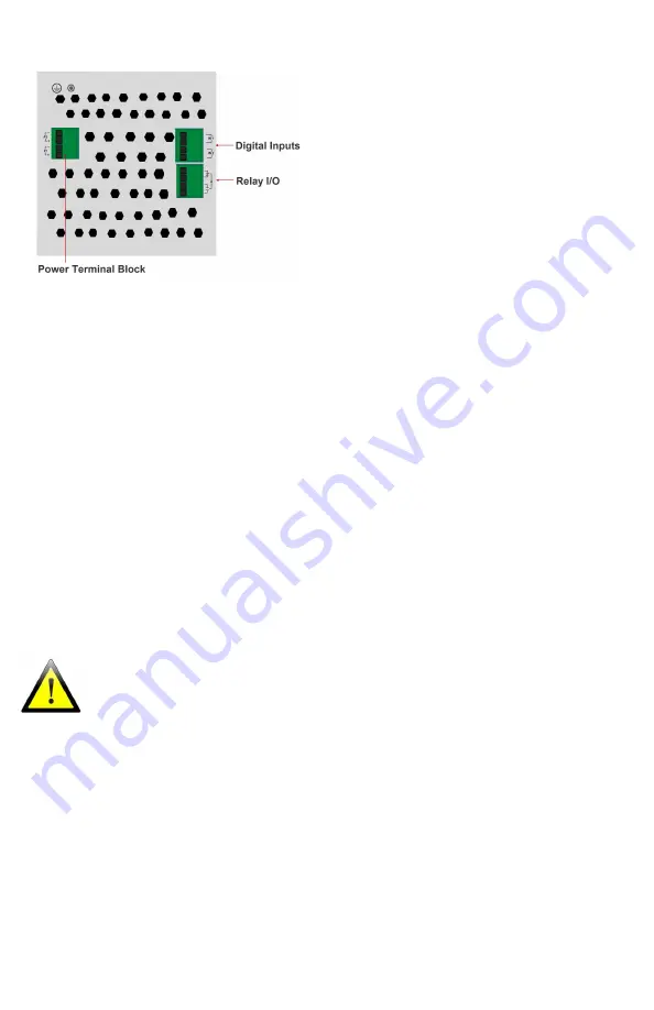
Wiring the Terminal Block
Connecting the switch to ground (optional)
If your installation requires additional grounding, refer to the Hardware Installation
Guide for information on connecting ground.
Connecting power to the IDS switch
You may connect both sets of power inputs to provide redundant power.
1.
Ensure the power source is off prior to connection.
2.
Using a pair of 12-16AWG wires, strip them both 7-8mm (5/16”).
3.
Loosen the terminal block screws and connect positive (+) / negative (-) wires in
the +/- terminals.
4.
Tighten terminal screws (0.51Nm torque). Ensure the wires are securely fastened.
5.
Re-insert the terminal block connector if removed. Turn power on at source. Check
LED indicators for status.
6.
Connect P2 (power source 2, beginning at Step 1.
For complete wiring instructions and for all Hazardous Locations and general safety warnings
consult the Hardware Installation Guide.


