IDS-206 Switches Quick Start Guide P/N 5500355-10 (Rev A)
3
Connecting a fiber device
Insert the SFP into an SFP slot and connect the appropriate fiber cable to the SFP.
Connecting Ethernet
Connect network or devices to Ethernet ports (1-5) using Cat5/5e Ethernet cables
LED Indicators
(For detailed information refer to the Hardware Installation Guide)
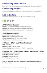
PWR (Power Inputs)
Green
—P1 and P2 Power inputs are within specifications
Orange
—P1 or P2 not providing power within specifications
Red
—Neither P1 or P2 providing power within specifications
SYS (System status)
Green blinking—System booting
Green solid—
System operating normally
Green blinking fast—
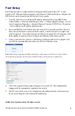
Fast Setup mode activated
Red—
Hardware fault or firmware load error
6 (Port 6
– SFP - Link/Activity status)
Off—
Link down
Green flashing—
Link and activity
Green blinking slowly—
Port in error disable or suspend state.
Ethernet Port Link / Speed (Green and Yellow LEDs)
1000 Mbps
Green on, Yellow off
100 Mbps
Green on, Yellow on
10 Mbps
Green off, Yellow on
Note: Flashing indicates activity
Note: Alr (Alarm), BC (Backup Coupling), RM (Ring Master) see Hardware
Installation Guide


