


4
User’s Handbook, TPD 1289E, Issue 2
27
6.3544 Series
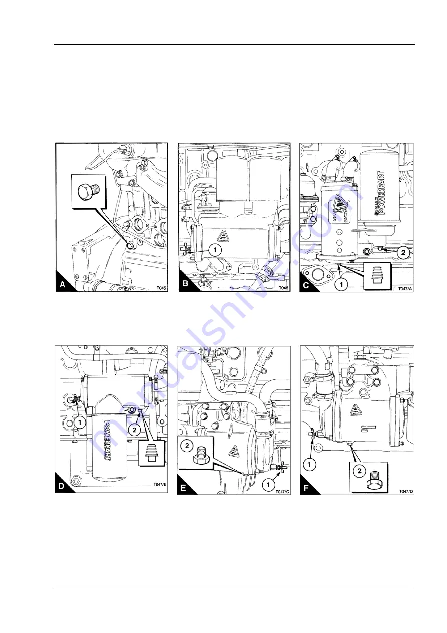
How to drain the cooling system
Caution:
Do not drain the coolant while the engine is still hot and the system is under pressure because
dangerous coolant can be discharged.
1
Ensure that the machine is on level ground.
2
Remove the filler cap of the cooling system.
3
Remove the drain plug from either side of the cylinder block (A) in order to drain the engine.
Note:
Ensure that the drain hole is not restricted.
4
Open the tap or remove the drain plug at the bottom of the radiator in order to drain the radiator. If the radiator
does not have a tap or drain plug, disconnect the hose at the bottom of the radiator.
5
If a lubricating oil cooler is fitted, open the drain tap or remove the drain plug (B1 or C1/D1/E1/F1) in order
to drain the coolant from the oil cooler.
Continued
This document has been printed from SPI². Not for Resale
Summary of Contents for 6.3544 Series
Page 6: ...vi This page is intentionally blank This document has been printed from SPI Not for Resale...
Page 48: ...42 This page is intentionally blank This document has been printed from SPI Not for Resale...
Page 52: ...46 This page is intentionally blank This document has been printed from SPI Not for Resale...
Page 56: ...50 This page is intentionally blank This document has been printed from SPI Not for Resale...