


Basic Engine
i02857720
Connecting Rod Bearings
Before you install the piston and piston pin, measure
the bore in the piston pin bearing. Before you install
the connecting rod, measure the bore in the bearing
for the crankshaft. The bores must be within
specifications or the bearings will not fit properly. This
will cause wear and damage to the connecting rod,
the bearing for the piston pin, the bearing for the
crankshaft, the piston pin, and the crankshaft.
After the bearings are installed, measure the bores in
the bearings. Refer to Specifications, “Connecting
Rod” for the correct measurements.
The length of a connecting rod can be altered by use.
After the bearings are installed, measure the distance
from the center of the piston pin bearing to the center
of the crankshaft bearing. Refer to Specifications,
“Connecting Rod” for the correct measurements.
Connecting rod bearings are available with 0.25 mm
(0.0010 inch) and 0.51 mm (0.020 inch) smaller
inside diameter than the original size bearing. These
bearings are for crankshafts that have been ground.
i02859895
Main Bearings
Main bearings are available with an inside diameter
that is 0.25 mm (0.010 inch) or 0.51 mm
(0.020 inch) smaller than the inside diameter of the
original bearings. These bearings are for crankshafts
that have been ground. Refer to Specifications,
“Connecting Rod” for further information.
If necessary, replace the main bearings. Refer to
Disassembly and Assembly, “Crankshaft Main
Bearings - Remove and Install” for the correct
procedure.
i02862425
Cylinder
Block
1.
Clean all of the coolant passages and the oil
passages.
2.
Check the cylinder block for cracks and damage.
3.
The top deck of the cylinder block must not be
machined. This will affect the depth of the cylinder
liner flange and the piston height above the
cylinder block.
4.
Check the front camshaft bearing for wear. Refer
to Specifications, “Camshaft Bearings” for the
correct specification of the camshaft bearing. If a
new bearing is needed, use a suitable adapter to
press the bearing out of the bore. Ensure that the
oil hole in the new bearing faces the front of the
block. The oil hole in the bearing must be aligned
with the oil hole in the cylinder block. The bearing
must be aligned with the face of the recess.
i06516674
Cylinder
Head
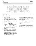
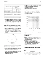
1.
Visually examine the valve face for damage (1).
Examine the valve stem for score marks, wear, or
damage near the groove for the valve keepers (3).
Illustration 15
g01425719
Typical example
2.
Check the dimension of the valve stem (2). Refer
to Specifications, “Cylinder Head Valves”.
M0064276
31


