


““
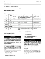
Warning/Derate
””
The
“
Diagnostic
”
lamp turns
“
ON
”
and the warning
signal (red lamp) is activated. After the warning, the
engine power will be derated. The warning lamp will
begin to flash when the derating occurs.
The engine will be derated if the engine exceeds
preset operational limits. The engine derate is
achieved by restricting the amount of fuel that is
available for each injection. The amount of this
reduction of fuel is dependent on the severity of the
fault that has caused the engine derate, typically up
to a limit of 50%. This reduction in fuel results in a
predetermined reduction in engine power.
““
Warning/Derate/Shutdown
””
The
“
Diagnostic
”
lamp turns
“
ON
”
and the warning
signal (red lamp) is activated. After the warning, the
engine power will be derated. The engine will
continue at the rpm of the set derate until a shutdown
of the engine occurs. The engine can be restarted
after a shutdown for use in an emergency.
A shutdown of the engine may occur in as little as 20
seconds. The engine can be restarted after a
shutdown for use in an emergency. However, the
cause of the initial shutdown may still exist. The
engine may shut down again in as little as 20
seconds.
If there is a signal for low oil pressure or for coolant
temperature, there will be a two second delay in
order to verify the condition.
For each of the programmed modes, refer to
Troubleshooting , “Indicator Lamps” for more
information on Indicator Lamps.
For more information or assistance for repairs,
consult your Perkins dealer or your Perkins
distributor.
i02788240
Sensors
and
Electrical
Components
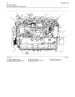
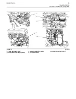
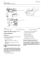
Sensor
Locations
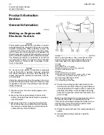
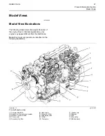
Illustration
shows
the
typical
locations
of
the
sensors
on
the
engine.
Specific
engines
may
appear
different
from
the
illustration
due
to
differences
in
applications.
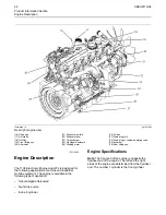
The
location
of
the
Electronic
Control
Module
(ECM)
is
illustrated.
SEBU8119-04
31


