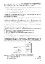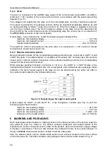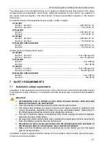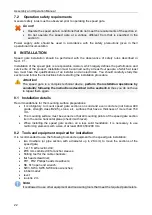
ST-02 Speed gate and STD-02 Double-sided section
7
4.2 Optional equipment
In addition to the standard delivery set, the following additional equipment can be supplied on a
separate order:
IR03.1
(HID/EMM), or
MR07 OEM
(Mifare), or
RP-15.2
(HID/EMM, Wiegand)
access card readers .......................................................................................... 2 per passage lane
Mounting kit for the mounting surface for each speed gate section:
PFG IH10 anchor (SORMAT, Finland)
..................................................................................... 6
M10×70 bolt with internal hexagon ........................................................................................... 6
washer 10 ................................................................................................................................. 6
Power supply
................................................................................................................................ 1
WRC device
................................................................................................................................ 1
5 OPERATION AND DESCRIPTION
5.1 Main features
•
The speed gate can operate in two main modes:
−
normally closed mode
– speed gate sliding panels are in closed position, when the power
is turned off, the sliding panels remain in the closed position and, if necessary, can be
moved apart manually (not locked);
−
normally open mode
– speed gate sliding panels are in the open position, when the power
is turned off, the sliding panels remain in the open position and do not lock the passage.
•
For normally-closed mode, it is possible to set an additional
Automatic opening in the
selected direction
operating mode in the pre-selected direction: the sliding panels
automatically open for each passage through the speed gate and close after the passage. The
mode can be set only for one direction; the second direction remains in the main operating
mode.
•
In all operating modes the speed gate sends an alarm signal if the passageway is locked for
more than 30 seconds.
•
Two levels of the passage sensors are installed along the entire length of the speed gate
passageway. This allows you to track the position of the user within the passageway, and also
allows multiple users to be in the passageway at the same time who are passing in the same
direction.
•
If necessary, the number of passage lanes through the speed gate can be increased by
installing
STD-02
double-sided sections.
•
It is possible to organize a checkpoint with passage lanes of different widths: 600 and 900 mm.
For this purpose, the following products should be used:
ST-02.600/900
(supplied upon request)
and
STD-02.900
with the sliding panel departure limiter installed on one side.
•
When organizing several passage lanes, the front end indication blocks allow the user to
choose the right passage in the right direction.
•
The speed gate supports two control modes: pulse and potential.
•
Speed gate can operate both as an operating device within the ACS, and as a standalone unit
controlled by operator from the RC-panel.
•
It is possible to install an external ACS controller and proximity readers inside the speed gate
section under the glass top cover.
•
The speed gate glass top cover features a built-in indication block, which combines a passage
grant/denial indicator and card interrogation zone indicator.
•
It is possible to connect remote indication blocks to duplicate the passage grant / denial
indication.
•
It is possible to connect a siren to the speed gate in order to warn the operator about
unauthorized passage attempts.
1
The WRC kit consists of a receiver, connected to the control board and a transmitter in the form of a fob.


