5
6
7
WARRANTY CARD
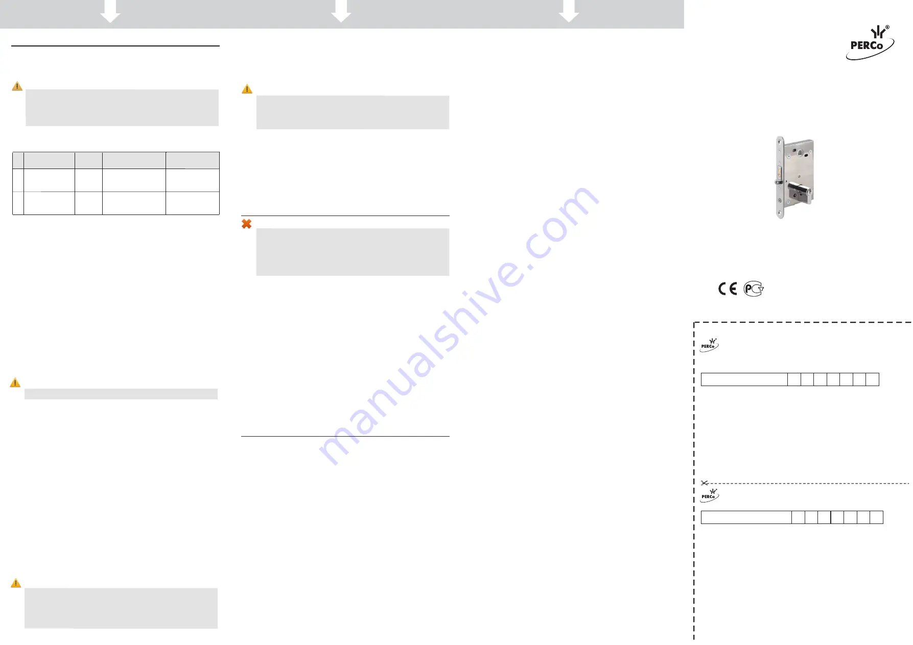
Electromechanical Lock LB-72.1
Serial number
Date of manufacture ________________ 201__
Quality Control Seal
_
_
_
_
_
_
_
_
_
_
_
_
_
_
_
_
_
_
_
_
_
_
Date of sale
«
» ________________ 201__
____________________________________
(signature, seal)
Cutting line
WARRANTY REPAIR COUPON
.1
.
2
7
-
B
L
k
c
o
L
l
a
c
i
n
a
h
c
e
m
o
r
t
c
e
l
E
Serial number
Date of manufacture ________________ 201__
Quality Control Seal
_
_
_
_
_
_
_
_
_
_
_
_
_
_
_
_
_
_
_
_
_
_
Date of sale
«
» ________________ 201__
____________________________________
(signature, seal)
Certificate and Operation Manual
www.perco.com
5. MAINTENANCE
6. PERCo WARRANTY
Electromechanical
Mortise Door Lock
- 1
.
2
7
B
L
РОСС RU.СП26
.
Н
ТУ
4981-049-8
8226999-2014
03587
6 6 3
6 6 3
4.3 Installation order
e
h
t
t
a
d
e
s
u
s
e
l
b
a
C
.
1
e
r
u
g
i
F
h
ti
w
e
c
n
a
d
r
o
c
c
a
n
i
n
e
v
i
g
e
r
a
s
r
e
b
m
u
n
e
c
n
e
r
e
f
e
R
installation are stated in Table 1.
Install the lock in the following order:
1. Unpack the lock and check the delivery set.
2. Carve out the installation template, which is included in the standard
delivery set. Make the hole marking for lock cylinder (6), lever rod (5) and,
if needed, of a location slot for lock forend plate (14) in the door leaf in
the place of lock installation using the template. Template marking
corresponds to the one in Fig. 2.
3. If necessary, select the locating pocket for the lock.
4. Carve out holes and choose the location slot for lock forend plate in
accordance with the marking.
5. Install the lock (7) in the locating pocket of the door and fasten it with two
screws 3.9×25 DIN7982 from the delivery set.
6. Mount the lock cylinder inside the lock and fix it with the screw through
the hole on the lock forend plate.
Attention!
Lock cylinder fastening screw length should not exceed 50 mm.
7. Adjust the door levers (1) with escutcheon plates (4) in accordance with
manufacturer recommendations. Tighten them with the screws with
threaded bushing (3). After the installation levers are to turn easily.
8. Check the lock operation at the opened door.
• Sink the locking mechanism ro
ller (12) inside the lock housing. The bolt
will move out of the lock housing (13). The lock will be closed.
•
Insert the key (2) inside the lock cylinder and turn it against stop to check
the mechanical unlocking. The bolt will return into an initial position inside
the lock housing.
• Energize lock flan
k contacts with 12V power supply to check the auto-
matic unlocking. The bolt will return into an initial position inside the lock
housing.
• Check several times.
9. Fix the strike plate (9) on the terminal block housing (10) with two screws
2.9×13 from the delivery set.
10. Make carving in the door according to the marking (Fig. 2).
11. Lay the control cable from the ACS to the terminal block installation place
inside the door frame. Use cable №1.
The cable laying method is deter-
mined by lock installer and the Customer.
12. Connect the control cable with terminal clamps (11) from the terminal
block. In order to do that, tighten cable ends into terminal clamps.
Attention!
If the lock is operated as a part of access control system (ACS) it
is recommended to install voltage regulator diode BZW06-15B or
P6KE16CA, or another model with equal parameters on contact
clips (Fig. 3). The voltage regulator diode is used for maintaining
the device which sends the control signal.
13. Mount the strike plate with the terminal block in the door frame providing
2-3 mm spacing between the strike plate and the forend when the door is
closed. The channel of the strike plate must lay symmetrical to bolt’s cross
section.
Attention!
The locking mechanism roller should not get into the channel of
the strike plate! Otherwise, at closing the door, it can get locked
with the moving roller and then it will be impossible to open the
door without damaging the lock.
14. Mount the strike plate on the door frame with two screws 3.9×25 from the
delivery set.
15. Install and connect the reed switch. Use cable №2 in table 1
for connec-
tion. Installing the reed switch ensure firm contact closure at closing the
door.
Disassembling of the lock should be made in the reverse order.
Warning!
•
Do not use the lock at power supply voltage other than specified
in its technical specifications.
• Do
not use the lock in operation conditions other than specified
in the following Manual.
•
Do not use the lock in hostile environment with atmospheric
content of acids, bases, oils, etc.
The lock is a normally-closed device, which means that in normal condition it
is locked at the closed door. In this case lever turning is blocked. After lock
release the door is opened by turning the lever (appro
x
imately at 20º).
Unlocking is performed by:
•
Turning the key in the lock cylinder. The key is to be turned against stop
and kept in such a position until the door opens.
•
Terminal block clamps’ energi
z
ing until the door opens. Energi
z
ing is
operated by the ACS controller. At that the potential operation mode
should be set for lock control output. Door opening detection is performed
according to the reed switch status.
At lock release the bolt moves inside the housing and the door can be
opened. At door opening the locking mechanism roller automatically moves
out of the lock housing.
At door closing the locking mechanism roller is sunk into the lock housing,
which initiates bolt moving-out and automatic locking.
PERCo (the Manufacturer) warrants that the LB72.1 electromechanical
mortise door lock (the Product) complies with applicable statutory safety
requirements, electromagnetic compatibility provided that the instructions on
storage, installation and operation, given in the Assembly & Operation Manual
are observed.
The warranty period is
5 (five) years
commencing from the date of sale.
Should there be no date of sale on the warranty card, the warranty period
shall commence from the date of manufacture.
Within the warranty period the Product is repaired free of charge at the
Manufacturer’s site.
The Warranty does not cover Products with e
x
ternal mechanical damages or
disassembled by the Customer.
Transportation cost to and back from the place of repair shall be borne by the
Customer.
Upon lock purchase request the date of sale stamp in the warranty certificate
and check the completeness of the delivery set as per the Manual.
In case any questions arise during the Product assembly or operation,
PERCo Company is always ready to give you necessary technical support.
4. ASSEMBLY AND INSTALLATION
4.1 General recommendations
The lock shall be installed by qualified professionals who have studied this
Manual before the installation work.
Attention!
In order to provide stable lock operation an accurate ±1,5 mm
vertical mounting of the strike plate with terminal block
regarding locking bolt is required. The lock operates normally
if the spacing between the forend plate and the strike plate is
2.5±1.5 mm.
4.2 Cable length
Table 1. Cables used.
№
Application
Max
length
Type of cable
An example
of cable
1 ACS controller
cable
30m
Twin cable with
0.75 mm
cross-section
2
HO3VV-F,
HO5VV-F 2×0.75
2
Reed switch
cable
30m
Twin cable with
0.2 mm
cross-section
2
RAMCRO
SS22AF-T
2×0.22 or CQR-2
PERCo
Polytechnicheskaya str., 4, block 2
194021, Saint Petersburg
Russia
Tel:
+7 812 247 04 64
E-mail: [email protected]
www.perco.com


