Pepperl+Fuchs schmersal RSS260 AS Operating Instructions Manual Download Page 4

4

Operating instructions

Safety sensor

RSS260 AS

EN

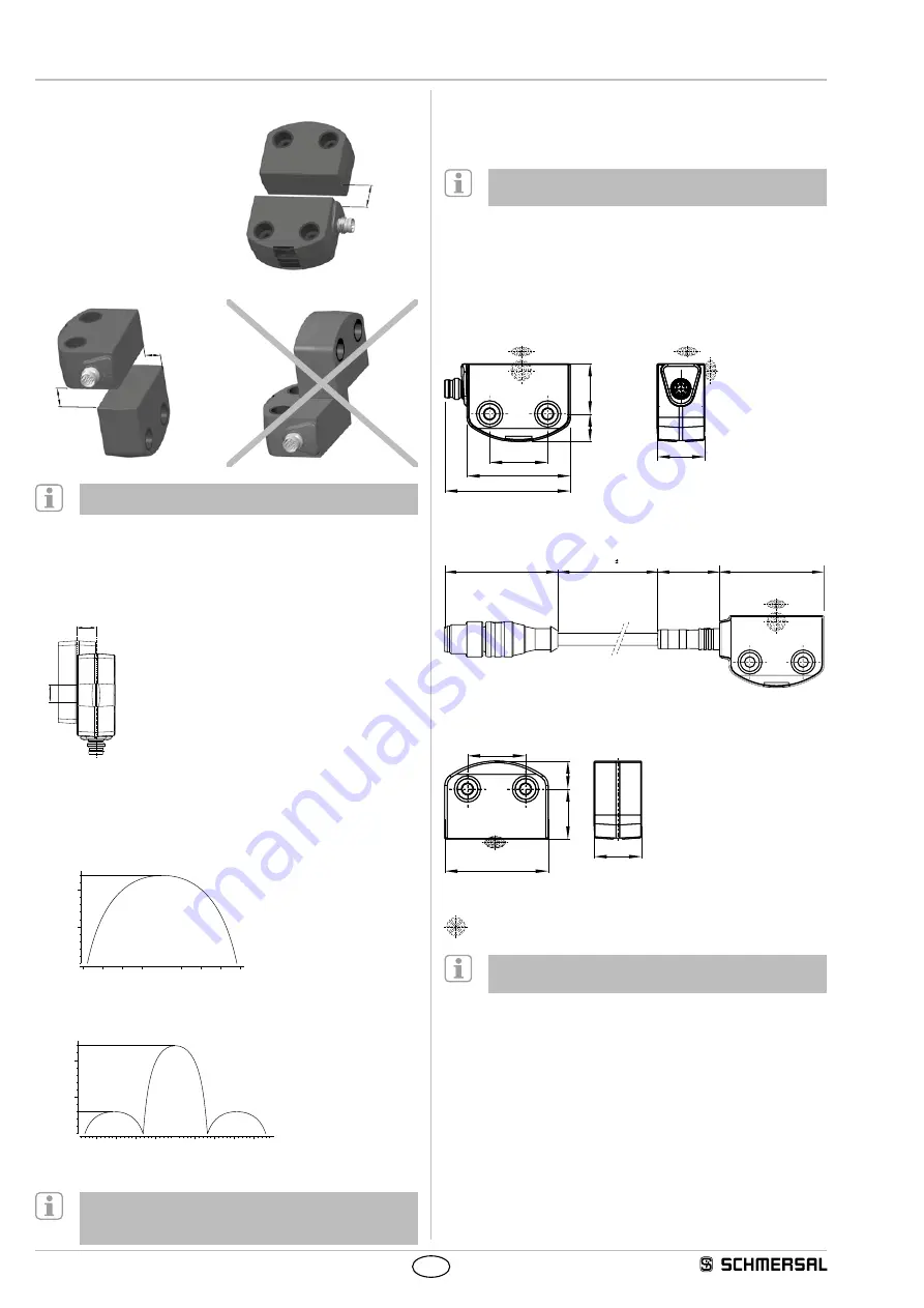
3.2  Actuating directions

Actuation from front

12

Actuation from side

9

7

Lateral actuation only from the shown sensor side

3.3  Switching distance

The side allows for a maximum height misalignment (X) of sensor 

and actuator of ± 8 mm (e.g. mounting tolerance or due to guard door 

sagging). The axial misalignment (Y) is max. ± 18 mm.

Y

X

Actuating curves

The actuating curves represent the typical switching distance of 

the safety sensor during the approach of the actuator subject to the 

actuating direction

Transverse misalignment

-5

-20

5

10 15

-15

20

-10

0

Y [mm]

S [mm]

0

5

10

12

Height misalignment

-5

-20

-24

5

10 15

-15

20 24

-10

0

X [mm]

S [mm]

0

5

10

12

Preferred actuation directions: from front or from side

In case of a lateral actuation, the switching distances are 

reduced by approx. 3 mm.

3.4  Adjustment

The continuous signal of the yellow LED signals the actuator detection; the 

flashing of the yellow LED after a delay signals that the safety sensor is 

actuated in the hysteresis area.

Recommended  Adjustment

Align the safety sensor and actuator at a distance of 0.5 x s

ao

.

The correct functionality of both safety channels must be checked by 

means of the connected safety-monitoring module.

3.5  Dimensions

All measurements in mm.

Safety sensor RSS260-…-ST-AS

19

10

.5

22

39.2

47.5

18

M4

Safety sensor RSS260-...-LSTM12-AS

43

25

47

250 


10

Actuator RST260-1 / RST260-1-AD01 … 15

19

10.5

39

22

18

M4

Legend:

active area

Alternative suitable actuators with different design:  

refer to products.schmersal.com.

3.6  Accessories

(to be ordered separately)

Kit tamper-proof screws

• 4 x M4x20 incl. washers, ordering code 103006158

• 4 x M4x25 incl. washers, ordering code 101217746

Sealing kit

• Ordering code 

103004733

•  Plugs: 4 flat pieces for flush finish and 4 round pieces for high screw 

heads to seal the installation holes 

•  Flush one-way plugs for flat screw heads, also suitable as tampering 

protection for the screw fixings 

Summary of Contents for schmersal RSS260 AS

Page 1: ...responsibility of the manufacturer of a machine or plant to ensure the correct functionality of the entire machine or plant The safety switchgear must be exclusively used in accordance with the versions listed below or for the applications authorised by the manufacturer Detailed information regarding the range of applications can be found in the chapter Product description Content 1 About this doc...

Page 2: ...ronic safety sensor is designed for application in safety circuits and is used for monitoring the position of movable safety guards In this application the safety sensor monitors the position of hinged sliding or removable safety guards by means of the coded electronic actuator The safety function consists of safely switching off the code transmission when the safety guard is opened and maintainin...

Page 3: ...essly approved by K A Schmersal GmbH Co KG could void the user s authority to operate the equipment L émetteur récepteur exempt de licence contenu dans le présent appareil est conforme aux CNR d Innovation Sciences et Développement économique Canada applicables aux appareils radio exempts de licence L exploitation est autorisée aux deux conditions suivantes 1 L appareil ne doit pas produire de bro...

Page 4: ... the yellow LED signals the actuator detection the flashing of the yellow LED after a delay signals that the safety sensor is actuated in the hysteresis area Recommended Adjustment Align the safety sensor and actuator at a distance of 0 5 x sao The correct functionality of both safety channels must be checked by means of the connected safety monitoring module 3 5 Dimensions All measurements in mm ...

Page 5: ...varying SaW code of a Safety at Work slave are evaluated through an OR operation with 4 inputs in the control system 5 4 Actuator teaching actuator detection Safety sensors with standard coding are ready to use upon delivery Individually coded safety sensors and actuators will require the following teach in procedure 1 Switch the safety sensor s voltage supply off and back on 2 Introduce the actua...

Page 6: ...Off 1 static 0 Internal device error periphery error red green flashing Flashes 1 1 static 0 AS i error slave address 0 or communication error red depending on the condition 0 static 0 1 refer to flash code Table 2 Error messages flash codes yellow LED Flash codes yellow Designation Autonomous switch off after Error cause 4 flash pulses Ambient temperature high 0 min Ambient temperature too high T...

Page 7: ...nctionality A regular visual inspection and functional test including the following steps is recommended 1 Check the safety function 2 Check the fixing and integrity of the safety switchgear the actuator and the cable 3 Remove possible metal chips Measures must be taken to protect against manipulation or against the bypassing of safety device for example using an extra actuator Damaged or defectiv...

Reviews: