background image

 2

0

2

0

-1

1

8

PCV...-F200-B17-V1D

Product Description

4.2

LED Indicators and Controls

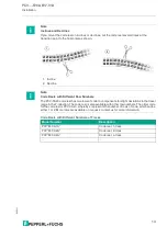
The PCV... read head is equipped with seven indicator LEDs for carrying out visual function 
checks and rapid diagnostics. The read head is equipped with two buttons on the back of the 
device for activating the alignment aid (see chapter 6.1) and the parameterization mode. Button 
1 is labeled ADJUST. Button 2 is labeled CONFIG.

Figure 4.1

ADJUST

CONFIG

1

2

LED 

1  2  3  4 

5  6  7

Summary of Contents for PCV F200-B17-V1D Series

Page 1: ...R PCV F200 B17 V1D Data Matrix Positioning System Manual ...

Page 2: ...sion as well as the supplementary clause Expanded reservation of proprietor ship Worldwide Pepperl Fuchs Group Lilienthalstr 200 68307 Mannheim Germany Phone 49 621 776 0 E mail info de pepperl fuchs com North American Headquarters Pepperl Fuchs Inc 1600 Enterprise Parkway Twinsburg Ohio 44087 USA Phone 1 330 425 3555 E mail sales us pepperl fuchs com Asia Headquarters Pepperl Fuchs Pte Ltd P F Bu...

Page 3: ... Connection 17 5 4 PROFINET Connection 19 6 Commissioning 20 6 1 Aligning the Read Head 20 7 Operation and communication 21 7 1 Communication via PROFINET 21 7 1 1 General Information on Communication via PROFINET 21 7 1 2 PROFINET I O Interface 21 7 1 2 1 Identification Maintenance I M Data 22 7 1 3 Project Planning Using Device Description 23 7 1 4 PROFINET Address and Identifying a Device 23 7 ...

Page 4: ...rldwide scale Symbols used The following symbols are used in this manual Handling instructions You will find handling instructions beside this symbol Contact If you have any questions about the device its functions or accessories please contact us at Pepperl Fuchs Group Lilienthalstraße 200 68307 Mannheim Germany Telephone 49 0 621 776 1111 Fax 49 0 621 776 271111 Email fa info de pepperl fuchs co...

Page 5: ...y 2020 11 5 2 Declaration of conformity 2 1 CE conformity This product was developed and manufactured under observance of the applicable European standards and guidelines Note A declaration of conformity can be requested from the manufacturer ...

Page 6: ...tenance and dismount ing lies with the plant operator Installation and commissioning of all devices may be performed only by trained and qualified personnel It is dangerous for the user to carry out modifications and or repairs and doing so will void the warranty and exclude the manufacturer from any liability In the event of any serious errors stop using the device Secure the device against unint...

Page 7: ...ounting rails and the read head is then mounted in parallel to a moving vehicle e g elevator car overhead conveyor chassis Maximum Length of the Code Tape This positioning system can be used with an appropriate resolution in equipment with extremely large layouts without restrictions The extensive yet user friendly parameterization options as well as the freely configurable inputs and outputs mean...

Page 8: ...dicator LEDs for carrying out visual function checks and rapid diagnostics The read head is equipped with two buttons on the back of the device for activating the alignment aid see chapter 6 1 and the parameterization mode Button 1 is labeled ADJUST Button 2 is labeled CONFIG Figure 4 1 ADJUST CONFIG 1 2 LED 1 2 3 4 5 6 7 ...

Page 9: ...lash 2 Hz Off Off Off Flashes green Off Off Off Alignment Z setpoint value fflash 2 Hz Off Off Off Flashes green Off Lights up Off Alignment Z setpoint value fflash 2 Hz Off Off Off Flashes green Off Flashes Off Alignment Z setpoint value fflash 2 Hz Off Off Off Flashes red Off Off Off Alignment Code tape outside read range fflash 2 Hz x x x Lights up red x x x System error x x x Lights up green x...

Page 10: ... in harsh ambient conditions appropriate Pepperl Fuchs accessories can be used to extend the service life of these products 1 Ask your contact person at Pepperl Fuchs Model number Description V19 G ABG PG9 FE Grounding terminal and plug set PCV SC12 PCV SC12A Grounding clip V1SD G M PUR ABG V1SD G PROFINET bus cable M12 to M12 available in several different lengths VAZ V1S B Stopping plug for M12 ...

Page 11: ...y or oily deposits and dust 2 Ensure that the surface is dry clean and stable 3 Pull the protective foil at the beginning of the code reel a few centimeters forward Place the code reel at the precise point of the required starting position on the underside and press to attach 4 Then affix the code reel along the desired travel range Remove the protective film gradually so that the code reel does n...

Page 12: ...Description PCV6M CA20 0 Code reel 2 track length 6 m PCV100M CA20 0 Code reel 2 track length 100 m Model Number Description PCV100M CA20 0 Code reel 2 track length 100 m starting position 0 m PCV100M CA20 10000 Code reel 2 track length 100 m starting position 100 m PCV100M CA20 990000 Code reel 2 track length 100 m starting position 9 900 m 000 009 0 m PXV AA25 www pepperl fuchs com Y Z X Caution...

Page 13: ...fferent Row Numbers The PCV CA20 code reel has two rows of code to compensate for slight deviations in the travel range in theY direction The code reel is also available with other row numbers The order code for the code reel is PCV CAx0 whereby x represents the number of rows of code which can be either 1 or 2 More rows are available on request contact us for more information Model Number Descrip...

Page 14: ...ferent threshold values will result depending on the number of tracks If the deviation exceeds this threshold a warning code is issued Y Axis Deviation Thresholds Hysteresis Y Axis Code reel Threshold Number of tracks Width Exit Entry 1 15 mm 10 mm 6 mm 2 25 mm 15 mm 11 mm 4 45 mm 25 mm 21 mm 6 65 mm 35 mm 31 mm 8 85 mm 45 mm 41 mm Y 0 X Y 0 X ...

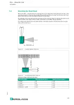
Page 15: ...ounting and the guidance of the moving system component must be such that the field of the depth of focus of the read head is not exited during operation The distance between the read head and the code tape should be the same as the read dis tance of the read head Figure 5 4 Vertical alignment tolerance Figure 5 5 Horizontal alignment tolerance Optimum Read Distance Z Axis Model Number Read Distan...

Page 16: ...20 20 Caution When selecting mounting screws ensure that the maximum insertion depth of the screws in the threaded inserts on the read head is 8 mm Using longer screws can damage the read head Caution The maximum torque of the mounting screws must not exceed 9 Nm Tightening the screws to a higher torque can damage the read head ...

Page 17: ...at this con nection Figure 5 7 Figure 5 8 Color Assignment Pepperl Fuchs single ended cordsets female are manufactured in accordance with EN60947 5 2 When using a type V19 see chapter 4 3 female cordset with an open cable end on the Main connection the colors are assigned as follows Connector Assignment Connection pin Strand color Color abbreviation 1 White WH 2 Brown BN 3 Green GN 4 Yellow YE 5 G...

Page 18: ...otential bonding cable is not laid or cannot be laid A film shield is used The following points relating to shielding must be noted Use metal cable clips that cover large areas of the shielding Place the cable shield onto the equipotential bonding rail immediately on entering the switch cabinet Direct the protective grounding connections to a common point in a star configuration The cross section ...

Page 19: ...or sockets M12 x 1 Profinet 1 and Profinet 2 on the side of the housing Figure 5 9 PROFINET connection diagram Figure 5 10 PROFINET connector assignment Suitable PROFINET cables can be found in the accessories section of the reader datasheet at www pepperl fuchs com Connector Assignment 1 2 3 4 TX RX TX RX Bus Profinet 1 2 1 3 4 2 ...

Page 20: ... If the distance is too great the yellow LED5 goes out The yellow LED5 flashes at the same time as the green LED2 when within the target range Set the distance between the read head and the code reel so that the yellow LED5 and the green LED2 flash synchronously Y coordinate If the optical axis of the read head is too low relative to the middle of the code reel the yellow LED4 lights up If the opt...

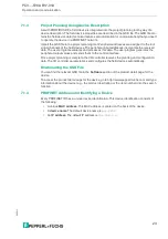
Page 21: ...in features of PROFIBUS DP The field device properties are written in a Generic Station Description Markup Language GSDML based on XML PROFINET IO is engineered in the same way as has long been the case for system integrators of PROFIBUS DP The decentralized field devices are assigned in the design of a controller PROFINET IO distinguishes between the following three device types IO controller Con...

Page 22: ...for example the installation location and installation date Maintenance data is initially stored in the device during installation Maintenance data can be changed Accessing and Editing I M Data The Step7 software from Siemens can be used to display and change the I M data 1 To do so open the hardware configuration HW Config and call up the Target system menu 2 Open one of the following functions D...

Page 23: ...es the peripheral output values and sends them to the control interface Once project planning is complete the I O controller receives the planning and configuration data The I O controller parameterizes and configures the field devices automatically Downloading the GSD File You can find the relevant GSD file in the Software section of the product detail page for the device To access the product de...

Page 24: ... X data MSB first MSB most significant byte Resolution 0 1 mm 1 mm 10 mm binary coded At a resolution of 1 mm and 10 mm Lmax 10 km 10 000 000 mm At a resolution of 1 mm and 10 mm Lmax 100 km1 100 000 000 mm 1 Version PCV100 F200 B17 V1D 6011 8203 up to 100 km measuring length Bit No Content Word 1 X Data Word 2 X Data 0 XP16 XP00 1 XP17 XP01 2 XP18 XP02 3 XP19 XP03 4 XP20 XP04 5 XP21 XP05 6 XP22 X...

Page 25: ... data 32 bit Y data MSB first Resolution 0 1 mm 1 mm 10 mm binary coded in two s complement Bit No Content Word 1 Y Data Word 2 Y Data 0 YP16 YP00 1 YP17 YP01 2 YP18 YP02 3 YP19 YP03 4 YP20 YP04 5 YP21 YP05 6 YP22 YP06 7 YP23 YP07 8 YP24 YP08 9 YP25 YP09 10 YP26 YP10 11 YP27 YP11 12 YP28 YP12 13 YP29 YP13 14 YP30 YP14 15 YP31 YP15 ...

Page 26: ...data 16 bit speed data Resolution 0 1 m s 0 01 m s 0 001 m s binary coded Speed of 0 12 5 m s Example Speed 4 7 m s speed output 47 at a resolution of 0 1 m s 65535 for unknown speed Bit No Content Word 1 Speed 0 SP00 1 SP01 2 SP02 3 SP03 4 SP04 5 SP05 6 SP06 7 SP07 8 SP08 9 SP09 10 SP10 11 SP11 12 SP12 13 SP13 14 SP14 15 SP15 ...

Page 27: ...n OUT XP 0 YP 0 SP 0 2 WRN Warnings present see Warning Module 3 EV EVENT present 4 posdetected Valid position information available 15 0 Error code Description Priority 1 Reader tilted 180 2 2 No clear position can be determined difference between codes is too great code distance incorrect etc 3 1000 Internal error 1 Size Type Content 1 words consistent Input data Last event marker Last event no ...

Page 28: ...Module Response Size Type Content 1 word consistent Input data Last warnings Last warning no Bit No Content Word 1 Last warning data 0 WRN01 1 WRN02 2 WRN03 3 WRN04 4 WRN05 5 WRN06 6 WRN07 7 WRN08 8 WRN09 9 WRN10 10 WRN11 11 WRN12 12 WRN13 13 WRN14 14 WRN15 15 WRN16 ...

Page 29: ... The sensor is just before OUT 4 WRN05 Y position too small The sensor is just before OUT 5 WRN06 The reader is rotated or tilted in relation to the code tape 6 WRN07 Low level of code contrast 7 WRN08 Repair tape detected 8 WRN09 Temperature too high 9 WRN10 Reserved 10 WRN11 Reserved 11 WRN12 Reserved 12 WRN13 Reserved 13 WRN14 Reserved 14 WRN15 Reserved 15 WRN16 Reserved Table 7 1 If no warning...

Page 30: ...velocity output Resolution 0 1 m s 0 01 m s 0 001 m s Horizontal Offset Offset in the direction of the X coordinate Length 0 mm 10 000 000 mm Input Function Function at input signal Function of input No Function Output1 Function Meaning of the output signal at output 1 Function of output No Function Overspeed Warning Error Event No Position Repair Strip Output2 Function Meaning of the output signa...

Page 31: ...0 mm 10 000 000 mm No Position Value Y Y value if no code tape is visible Y data at No Position Last Valid Posi tion Specified Posi tion 0 mm 10 000 000 mm No Position Value Speed Speed value if no code tape is visible Speed data at No Position Last Valid Speed Specified Speed 0 mm s 65 534 mm s Table 7 2 Bold default values Designation Function Parameter data Primary data ...

Page 32: ...t absolute position of the code strip before it entered the event range and adds the incre mental offset from the codes of the event markers When the reading head enters the range of an event marker it sets an event flag in the output data You also have the option of triggering a defined action when an event occurs by parame terizing one of the outputs accordingly see chapter 7 1 Actions of this t...

Page 33: ... to repair tape Note When placing a repair tape on the code reel make sure that the repair tape represents as accurate a continuation of the grid on the code reel as possible Note The repair tape works incrementally In so doing it adds one value to the previous read position on the code reel If the read head starts on a repair tape the read head reports an error Move the read head to a position on...

Page 34: ...2B 43 4B 75 K 6B 107 k 0C 12 FF 2C 44 4C 76 L 6C 108 l 0D 13 CR 2D 45 4D 77 M 6D 109 m 0E 14 SO 2E 46 4E 78 N 6E 110 n 0F 15 SI 2F 47 4F 79 O 6F 111 o 10 16 DLE 30 48 0 50 80 P 70 112 p 11 17 DC1 31 49 1 51 81 Q 71 113 q 12 18 DC2 32 50 2 52 82 R 72 114 r 13 19 DC3 33 51 3 53 83 S 73 115 s 14 20 DC4 34 52 4 54 84 T 74 116 t 15 21 NAK 35 53 5 55 85 U 75 117 u 16 22 SYN 36 54 6 56 86 V 76 118 v 17 2...

Page 35: ...Pepperl Fuchs Quality Download our latest policy here www pepperl fuchs com quality www pepperl fuchs com Pepperl Fuchs Subject to modifications Printed in Germany DOCT2907E ...

Reviews: