background image

Functional Safety KCD2-RR2-Ex1(.SP)

Operation

20

19

-1

1

15

Proof Test Procedure

1. Put out of service the entire safety loop. Protect the application by means of other measures.
2. Connect a current source to terminals 7 and 8, see figure. Depending on the application, 

the current source should supply 200

µ

A to 10 mA.

3. Connect a RTD simulator, see figure. Configure the device via the DIP switch according 

to the application.
• For 4-wire connection: to terminals 1, 2, 3 and 4, DIP switch S1 in position II

• For 3-wire connection: to terminals 2, 3 and 4, DIP switch S1 in position I

• For 2-wire connection: to terminals 2 and 4, DIP switch S1 in position II

4. Secure the DIP switch to prevent unintentional adjustments. Close the cover.
5. Connect the digital multimeter to terminals 7 and 8, see figure.
6. Set the combinations of excitation currents and resistances, see table. 

Use the current source and the RTD simulator.

 The proof test is passed if the following voltage values are measured, see table.

7. To test the correct lead breakage detection, open the connections at 

terminals 1, 2, 3 and 4 

individually

.

 The proof test is passed if the resistance signaled on the digital multimeter 

for all excitation currents is between < 15

or > 400

.

 The proof test is passed if the resistance signaled on the digital multimeter 

for a excitation current < 1 mA is between < 15

or > 4 k

.

8. To test the correct lead breakage detection, open 

all

 connections at 

terminals 1, 2, 3 and 4.

 The proof test is passed if the resistance signaled on the digital multimeter 

for all excitation currents is between < 15

or > 400

.

 The proof test is passed if the resistance signaled on the digital multimeter 

for a excitation current < 1 mA is between < 15

or > 4 k

.

9. Set back the device to the original settings for the application after the test.

Resistance

Excitation current
200 

A

1 mA

10 mA

100 

0.02 V

±

1.25 mV

0.1 V

±

0.25 mV

1 V

±

2.5 mV

400 

0.08 V

±

5 mV

0.4 V

±

1 mV

4 V

±

10 mV

1 k

0.24 V

±

15 mV

1.2 V

±

3 mV

4 k

0.8 V

±

50 mV

4 V

±

10m V

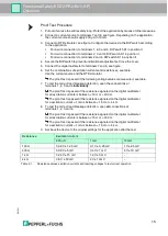
Table 5.1

Resistance values, excitation currents and resulting voltages to test correct operation

Summary of Contents for KCD2-RR2-Ex1

Page 1: ...ISO9001 2 Functional Safety Resistance Repeater KCD2 RR2 Ex1 SP PROCESS AUTOMATION MANUAL ...

Page 2: ...elivery for Products and Services of the Electrical Industry published by the Central Association of the Electrical Industry Zentralverband Elektrotechnik und Elektroindustrie ZVEI e V in its most recent version as well as the supplementary clause Expanded reservation of proprietorship Functional Safety KCD2 RR2 Ex1 SP ...

Page 3: ...on 7 2 2 Interfaces 7 2 3 Marking 7 2 4 Standards and Directives for Functional Safety 7 3 Planning 8 3 1 System Structure 8 3 2 Assumptions 9 3 3 Safety Function and Safe State 10 3 4 Characteristic Safety Values 11 3 5 Useful Lifetime 12 4 Mounting and Installation 13 4 1 Configuration 13 5 Operation 14 5 1 Proof Test 14 6 Maintenance and Repair 17 7 List of Abbreviations 18 ...

Page 4: ...oting Dismounting Disposal The documentation consists of the following parts Present document Instruction manual Manual Datasheet Additionally the following parts may belong to the documentation if applicable EU type examination certificate EU declaration of conformity Attestation of conformity Certificates Control drawings FMEDA report Assessment report Additional documents For more information a...

Page 5: ...d and understood the instruction manual and further documentation Intended Use The device is only approved for appropriate and intended use Ignoring these instructions will void any warranty and absolve the manufacturer from any liability The device is developed manufactured and tested according to the relevant safety standards Use the device only for the application described with specified envir...

Page 6: ...re displayed in descending order as follows Informative Symbols Action This symbol indicates a paragraph with instructions You are prompted to perform an action or a sequence of actions Danger This symbol indicates an imminent danger Non observance will result in personal injury or death Warning This symbol indicates a possible fault or danger Non observance may cause personal injury or serious pr...

Page 7: ...715 2 2 Interfaces The device has the following interfaces Safety relevant interfaces input and output 2 3 Marking 2 4 Standards and Directives for Functional Safety Device specific standards and directives System specific standards and directives Note For corresponding connections see datasheet Pepperl Fuchs Group Lilienthalstraße 200 68307 Mannheim Germany Internet www pepperl fuchs com KCD2 RR2...

Page 8: ...he demand rate for this safety loop is assumed to be higher than once per year The relevant safety parameters to be verified are the PFH value Probability of dangerous Failure per Hour Fault reaction time of the safety system the SFF value Safe Failure Fraction the HFT architecture Hardware Fault Tolerance 3 1 3 Safe Failure Fraction The safe failure fraction describes the ratio of all safe failur...

Page 9: ...e failure rates must be multiplied by a factor of 2 5 based on experience A similar factor must be used if frequent temperature fluctuations are expected The application program in the programmable logic controller PLC is configured to detect underrange and overrange failures The device do not has a fault bus SIL 2 Application The device shall claim less than 10 of the total failure budget for a S...

Page 10: ...tached PLC must recognize a fault when the resistance drops below 15 or rises above 400 for Pt100 or above 4 k for Pt1000 The switch position of the DIP switch on the device has no influence on the safety function Safe State The safe state of the output is the high impedance state 100 k or the fault state 15 Reaction Time The reaction time for all safety functions is 20 ms Note See corresponding d...

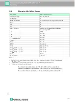
Page 11: ...FT 0 SIL 2 SC 3 Safety function Transfer of the resistance values with an accuracy of 2 s 1 0 FIT dd 134 FIT du 54 4 FIT total safety function 1 188 FIT not part 377 FIT SFF 1 71 1 MTBF 2 164 years PFH 5 44 x 10 8 1 h PFDavg for T1 1 year 2 38 x 10 4 PFDavg for T1 2 years 4 77 x 10 4 PFDavg for T1 3 years 7 15 x 10 4 PTC 100 Reaction time 3 20 ms Table 3 1 1 No effect failures are not influencing ...

Page 12: ...is assumed that early failures are detected to a huge percentage during the installation and therefore the assumption of a constant failure rate during the useful lifetime is valid However according to IEC EN 61508 2 a useful lifetime based on general experience should be assumed Experience has shown that the useful lifetime often lies within a range period of about 8 to 12 years As noted in DIN E...

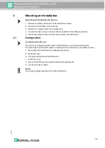
Page 13: ...n 5 Check the safety function to ensure the expected output behavior 4 1 Configuration Configuring the Device The device is configured via DIP switch The DIP switch is on the front of the device The switch position of the DIP switch on the device has no influence on the safety function 1 De energize the device before configuring the device 2 Open the cover 3 Configure the device via the DIP switch...

Page 14: ... Check the function of the subsystem at periodic intervals depending on the applied PFDavg in accordance with the characteristic safety values See chapter 3 4 It is under the responsibility of the plant operator to define the type of proof test and the interval time period Equipment required Digital multimeter with an accuracy better than 0 1 Use for the proof test of the intrinsic safety side of ...

Page 15: ... the following voltage values are measured see table 7 To test the correct lead breakage detection open the connections at terminals 1 2 3 and 4 individually The proof test is passed if the resistance signaled on the digital multimeter for all excitation currents is between 15 or 400 The proof test is passed if the resistance signaled on the digital multimeter for a excitation current 1 mA is betw...

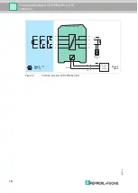
Page 16: ... Safety KCD2 RR2 Ex1 SP Operation Figure 5 1 Proof test set up for KCD2 RR2 Ex1 SP KCD2 RR Ex1 SP Zone 0 1 2 Div 1 2 Zone 2 Div 2 Multimeter V 9 10 I supply 8 7 6 5 4 3 1 2 24 V DC Power supply Supply 4 mA to 20 mA I supply ...

Page 17: ...es not work Take appropriate measures to protect personnel and equipment while the safety function is not available Secure the application against accidental restart 3 Do not repair a defective device A defective device must only be repaired by the manufacturer 4 If there is a defect always replace the device with an original device Danger Danger to life from missing safety function Changes to the...

Page 18: ...e is not used for calculation of SFF not part Probability of failure of components that are not in the safety loop total safety function Probability of failure of components that are in the safety loop HFT Hardware Fault Tolerance MTBF Mean Time Between Failures MTTR Mean Time To Restoration PCS Process Control System PFDavg Average Probability of dangerous Failure on Demand PFH Average frequency ...

Page 19: ...Functional Safety KCD2 RR2 Ex1 SP Notes 2019 11 19 ...

Page 20: ...rl fuchs com Worldwide Headquarters Pepperl Fuchs Group 68307 Mannheim Germany Tel 49 621 776 0 E mail info de pepperl fuchs com For the Pepperl Fuchs representative closest to you check www pepperl fuchs com contact PROCESS AUTOMATION PROTECTING YOUR PROCESS DOCT 6482A 11 2019 ...

Reviews: