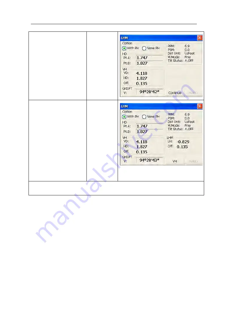
Pentax W-1502N Series Instruction Manual Download Page 63

53

Collimate

ground

point

G

by

screwing

vertical tangent part.

Collimate

G

Click “Continue” key

again, and then height

of

overhead line(LH)

and

horizontal

distance(Off)

will

display.

1)

~※

3)

Continue

1) Click “X” key to end measurement.

2) Click “VH” key to return operation step

.

Summary of Contents for W-1502N Series

Page 1: ...W 1502N Series Total Station Instruction Manual ...

Page 2: ...eliable instrument whose performance and design are not surpassed To fully appreciate and protect your investment we suggest that you take the necessary time to read and fully understand this manual We have a dedicated service organization If the need arises please don t hesitate to call us Thank you for your trust and confidence ...

Page 3: ... tight High temperature condition If put the instrument in high temperature condition for a long time it is bad for the instrument performance Temperature changing sharply The sharp temperature changing on the instrument or prism will shorten the distance measurement range for example after taking the instrument out from a warm car to a cold condition wait for some time it can be used when it adap...

Page 4: ...ult fire when charging If use defection power cable socket or plug there is danger of fire or electronic shock Using wet battery or charger maybe result fire or electronic shock Do not close the instrument to burning gas or liquid and do not use the instrument in coal mine Blast could be result Do not put the battery in the fire or high temperature condition Explosion damage could result If use th...

Page 5: ...le the tribrach carefully if the tribrach is not stable series damage could result Drop the instrument or tripod series damage could result Before use it check the central screw is tight User 1 This product is for professional user only The user is required to be a qualified surveyor or have a good knowledge of surveying in order to understand the user manual and safety instructions before operati...

Page 6: ...nnecting with other products Safety Standards for Laser W 1502N series adopts the safe and visible laser on the basis of Specification Standard of radiant products FDA CDRH 21CFR Part 1040 10 and 1040 11 and Safety of laser products parts 1 Equipment classification requirements and user s guide IEC 60825 1 2001 According to above standards W 1502N series is class Ⅲa 3R laser products When the pris...

Page 7: ...rious injury Never look directly into the laser beam source it could cause permanent eye damage Never stare at the laser beam it could cause permanent eye damage Never look at the laser beam through a telescope or other optical devices it could cause permanent eye damage WARNING ...

Page 8: ...USB connection 11 1 8 Guide light Optional 12 2 Preparation before Measurement 13 2 1 Setting up the instrument 13 2 2 Levelling Up 13 2 3 Centering 16 2 3 1 Centering with Optical Plummet Optional 16 2 3 2 Centering with Laser Plummet 16 3 Instrument settings 17 3 1 INST Setup 17 3 1 1 Setting the measure condition 18 3 1 2 Setting the units 18 3 1 3 Setting parameters of communication ports 19 3...

Page 9: ...urement MLM 42 4 4 8 Line height Measurement 45 4 5 Coordinate Measurement Mode 50 4 5 1 Setting coordinate of occupied point 50 4 5 2 Setting backsight point 51 4 5 3 Setting instrument height and prism height 53 4 5 4 Operation of coordinate measurement 54 4 5 5 Traverse Surveying 55 4 5 6 Offset Measurement Mode 58 4 6 About 68 5 Check and Adjustment 69 5 1 The Instrument Constant 69 5 2 Plate ...

Page 10: ...3 82 Appendix II Correction for refraction and earth curvature 84 Appendix III Assembling and disassembling for three jaw tribrach 85 ...

Page 11: ...1 1 Nomenclature and Functions 1 1 Nomenclature Handle Optical sight Touch Keypad Handle Instrument height Objective Touch pen Circular level ...

Page 12: ...2 Battery clamp Plate Horizontal clamp knob USB port Tribrach clamp Eyepiece Vertical tangent knob Vertical clamp knob Horizontal tangent Battery clamp ...

Page 13: ...α Shift key for character entry The current entry method can shift among number smaller letter and capital letter Star key Normal configurations can be set here Tab Tab key Move the cursor right or next position BS BackSpace key Move the cursor left and delete one character Ctrl Ctrl key Same with the Ctrl key of PC Space Space key Enter the space Enter Enter key Confirm an entry or selection ESC ...

Page 14: ...4 by program screen Navigation key Control the focus bar within the screen and the entry bar within a field ⓛ Power key Turn on off the instrument ...

Page 15: ...ius INST Setup Instrument Setup and About Relevant Information 1 3 1 Basic Measurement Function introduction Display Click BSC Measure key to activate basic measuring This function is used for simple measuring and calculating including angle measurement distance measurement coordinate measurement and parameter setting Distance measurement mode underpins Remote Elevation Measurement and Line height...

Page 16: ...ulate applied measurements during conventional surveying It contains project management import export instrument station setup and orientation foresight measurement backsight measurement side looking measurement cross sectional measurement setting out of point bunch and alignment road design traverse adjustment coordinate geometry batter board label steel ruler connection survey data query and edi...

Page 17: ...series of functions such as compensator linear correction compensator zero correction horizontal axis error correction index correction instrument settings distance constant settings communication port settings configuration management etc 1 3 4 About Function introduction Display The About function Offers information of manufacturer and software version 1 3 5 Professional field software Function ...

Page 18: ...bject illumination prism constant and communication port are provided 1 4 Shortcut key 1 Some shortcut keys are applied in 350 series Key combination Description Power on off Enter into setting mode directly turn on the electronic bubble α Shift among number smaller letter and capital letter FUNC BS Enter this combinition at the same time before starting up to backup all settings FUNC CTRL Enter t...

Page 19: ...keyboards FUNC Increase backlight brightness of LCD FUNC Decrease backlight brightness of LCD FUNC Turn on off LCD display in face left position FUNC Turn on off LCD display in face right position 2 method for character entry switch Press α key current character entry mothod will be changed on the lower right corner the inputing method will display for a moment ...

Page 20: ...rocess is shown in the figure below 1 Carefully press and briefly hold stylus on the center of the target Repeat as the target moves around the screen 2 After all the targets are clicked the screen will display as left tap the screen to register saved data The screen goes back to Stylus Properties menu 1 6 Battery 1 6 1 Battery Power indicator At any screen press key to open fast setting menu Sele...

Page 21: ...antaneous power change And if the measurement mode changes the symbol will not show the power s decrease or increase immediately 4 It is suggested that user should check every battery power before field work 1 6 2 Replace and mount battery Two battery are equipped with W 1502N any one can work individually so it is possible to take off one battery for recharging when the instrument is working 1 Ba...

Page 22: ...V 240V power supply The red lamp becomes lighting which indicates recharging If interval time is longer the connector isn t fixed well 3 That the green lamp flashes means recharging is complete NOTE 1 New battery or battery does not used for several months should be recharged for several times Please recharge it more than 10 hours and then the battery can attain best status 2 Please recharge the b...

Page 23: ... could be used by USB Host connector The file in the external memory stick could be read in the instrument interface 1 Open the cover of USB which behind the display panel 2 Input external memory stick into USB Host connector 3 The external memory stick could be recognized as hard disk automatically It could be file copy etc ...

Page 24: ... and others Under the face left the Surveyor should move to left direction when he only saw the green light or the light became bigger If only saw the red light or red light became bigger the surveyor should move to the right direction The move direction will be contrary when the telescope is in face right Guide light on off press to open fast setting menu select Battery if the instrument is equip...

Page 25: ...hoes are firmly fixed in the ground 2 Attaching the instrument on the tripod head mount the instrument carefully on the tripod head Supporting it with one hand tighten the centering screw on the bottom of the unit to make sure it is secured to the tripod 2 2 Levelling Up 1 Basic Levelling Up with the circular level 1 Move the foot screws A and B in opposite direction till the circular bubble is pe...

Page 26: ...ble in the center of the level 3 Repeat above steps until the bubble remains in the center of the plate level while the instrument is rotated to any position 3 Accurate Levelling Up with Electronic Level on the screen It is convenient for W 1502N series to level up with electronic level especially when it is difficult to observe the circular level and plate level Firstly press the key to turn on t...

Page 27: ...the bubble is in the plate level Make sure the red spot is in the center Note As shown you can realize transformation of compensation options by pressing the lower right button XYON compensate horizontal angle and vertical angle at the same time XONYOFF just compensate X axis XYOFF don t compensate X axis and Y axis A OFF don t compensate X axis and Y axis and turn off the popup function of electr...

Page 28: ...ss Thus that laser emits downwards can be seen Loosen the center screw of tripod and move the base plate on tripod head until the laser spot coincides with ground mark point Then tighten the center screw Repeat leveling and two steps until the instrument keeps leveling and the laser spot coincides with ground mark point when rotating alidade of instrument in any direction After centering please tu...

Page 29: ...tion and management of instrument constant It is made up of a serie of functions such as compensator linear correction compensator zero correction horizontal axis error correction index correction instrument settings distance constant settings communication port settings configuration management etc 3 1 INST Setup ...

Page 30: ...nfiguration settings screen On the screen tap or keys different setting screen can be shifted NOTE This password is open for all users current configuration settings can be checked here but not be adjusted If you want to adjust these settings please contact local distributer or PENTAX company Tap or keys to display other settings ...

Page 31: ...0 142 K 0 2 No 5 Sea Level correction mode will be Yes or No 6 Target Type mode will be Prism No Prism Reflector You could press Enter to keep the setting or press cancelled 3 1 2 Setting the units Operation 1 Angle unit mode will be DMS GON MIL 2 Angle Precision mode will be 1 second 0 1 second or 0 5 second 3 Distance Unit mode will be Meter US Feet Feet 4 Distance precision mode will be 1mm or ...

Page 32: ...ication ports As left shows click Other Setup you can activate bluetooth BT and guidelight GL and set parameters of Bluetooth Port and Phy Port 3 1 4 Instrument parameters review Click Data Monitor used for reviewing the setting parameters ...

Page 33: ...cluding Cross Light Guide Light and Laser Point Cross Light Click this item to turn on the reticle illumination and move the slipping button to adjust reticle illumination Guide Light Click Battery key resulting in display on which guide light could be adjusted Laser Point Tun on off the laser flash before distance measurement ...

Page 34: ...orizontal angle as zero S Angle Set current horizontal angle L Angle Lock horizontal angle Repeat Retest horizontal angle V Switch between vertical angle and percent grade L R Angle Horizontal angle switch between left and right Mode Set Fine N Fine Loop Fine Track measurement mode m ft Switch among meter international feet and American feet in terms of distance unit Setout Set out measurement mod...

Page 35: ... displayed coordinate order as NEZ or ENZ Save Coor Save coordinate of instrument station or not Ang Unit Set Ang Unit as DMS GON MIL Dist Unit Set Dist Unit as m UsFeet IntFeet Stop Stop distance measurement Exit Exit basic measurement program 4 3 Angle measurement mode 4 3 1 Horizontal angle right angle and vertical angle measurements At first make sure the operation is under angle measurement m...

Page 36: ...imate the second first target B and the horizontal angle and vertical angle will display on the screen of instrument Collimate B 4 3 2 Horizontal angle switch between right and left Make sure the operation is under angle measurement mode Operation steps Keys Display Make sure the operation is under angle measurement mode ...

Page 37: ...ery time you click the L R Angle key 4 3 3 Setting horizontal angle with the L Angle key Make sure the operation is under angle measurement mode Operation steps Keys Display Turn horizontal circle unit in the needed direction with horizontal clamp and tangent part Click L Angle key and activate the function of locking horizontal angle L Angle ...

Page 38: ...ill return normal angle measurement mode and meantime horizontal angle will be set as locked angle Unlock 1 Click Cancel key before it returns to Previous mode 4 3 4 Setting horizontal angle with the S Angle key Make sure the operation is under angle measurement mode Operation steps Keys Display Collimate target point used for Orientation ...

Page 39: ...gle input horizontal angle With data entry complete click Enter key and angle measurement after orientation will go on Enter 1 Data entry should be refered to the format shown in the dialog box 4 3 5 Setting vertical angle and percent grade mode with the V key Make sure the operation is under angle measurement mode Operation steps Keys Display ...

Page 40: ...and percent grade will be switched in turn every time you click V key 4 3 6 Carrying out angle retesting with the Repeat key This program is applied for adding up angle retesting values displaying the sum and the average of all observed values and meantime recording the number of observations ...

Page 41: ...31 Operation steps Keys Display Click Repeat key and activate angle retesting function Repeat ...

Page 42: ...32 Collimate the first target A Collimate A Click S Zero key and set horizontal angle as zero S Zero Collimate the second target B using horizontal clamp and tangent part Collimate B ...

Page 43: ... Collimate the second target B again using horizontal clamp and tangent part Click L Angle key And then the screen displays the sum and the average of all angles 1 Collimate B again L Angle Repeat steps according to the requirement and carry out angle retesting 2 1 Click Exit key to finish angle retesting 2 Ht the sum of multiple observed values ...

Page 44: ...34 Hm the average of multiple observed values 4 4 Distance measurement mode 4 4 1 Distance measurement and measuring mode setting Operation steps Keys Display Collimate the centre of prism Collimate ...

Page 45: ...ck Mode key to activate setting function of distance measurement mode Take Loop Fine as example here Fine single fine measuring mode N Fine n times fine measuring mode Loop Fine Continuous measuring mode Track tracking measuring mode Mode Display the result of measurement 1 2 1 Click mode key if you wanna change measurement mode as step shows ...

Page 46: ...set single observation the average distance won t be displayed In general the factory default is set as single observation Operation steps Keys Display Under distance measurement mode click Mode key to activate setting function of distance measurement mode The default setting is single observation Mode Click N Fine key with stylus and then input the number of needed observations in the upper right...

Page 47: ... 1 Click M Ang key to return angle measurement mode 4 4 3 Accurate Measurement and Track mode Accurate Measurement mode it s a normal measurement mode Track mode Track mode takes less time than accurate measurement It is mainly applied for setting out survey and useful for tracking moving target Operation steps Keys Display ...

Page 48: ...stance measurement mode And this mode is set as Track Mode Click Enter key collimate the centre of prism and the system will carry out measurement based on previous setting Enter 4 4 4 Exchange of distance units Change distance unit on the screen of distance observation Operation steps Keys Display ...

Page 49: ...time you click m ft key 4 4 5 Distance stake out measurement This function can display the difference between measured distance and preset distance Displayed Value Observed Value Standard Preset Distance Setting out among all sorts of distance measurement modes such as slope distance horizontal distance and elevation difference can be carried on Operation steps Keys Display ...

Page 50: ...et out is displayed in the popup dialog box Click Enter key to execute SD setting out after inputing data If you want HD setting out need to input zero in SD dialog box click Enter and the system will eject HD dialog box automatically HD setting out can go on after HD data entry If you want VD setting out need to input zero in both SD dialog box and HD dialog box thus the system will remind you to...

Page 51: ...ment will start from the prism reference point If no prism height is used the remote elevation will start from any reference point in which the vertical angle is established In both modes the reference point should be perpendicular to the remote object 1 With prism height PH input Operation steps Keys Display Under distance measurement mode click REM key to activate remote elevation measurement RE...

Page 52: ...ith stylus with PH Input the prism height following PH Input prism height Collimate the centre P of prism Click M Dist key to start measuring Horizontal distance between instrument and prism will be shown Collimate prism M Dist ...

Page 53: ...d position of prism is locked that means reference point is confirmed Continue Collimate target K and click Continue vertical distance VD will be shown 1 Collimate K 1 Click Exit key to finish REM 2 without prism height input ...

Page 54: ... None PH Collimate the ground point Click M Dist key to start observing Horizontal distance between instrument and prism will be shown Collimate prism M Dist Click Continue key and position of ground point G is locked that means reference point is confirmed Continue ...

Page 55: ...45 Click Continue key Continue Collimate remote target K Vertical distance VD will be shown 1 Collimate target 1 Click Exit to finish REM ...

Page 56: ...surement program calculates the horizontal distance dHD slope distance dSD and elevation dVD between two target prisms The instruemt can accomplish this in two ways 1 MLM Method A B A C Measurement is A B A C A D 2 MLM Method A B B C Measurement is A B B C C D ...

Page 57: ...splay Under distance measurement click MLM key to activate Missing Line Measurement MLM Select method A B A C with stylus Collimate prism A click M Dist key Horizontal distance between instrument and prism A will be shown M Dist ...

Page 58: ...D elevation difference dVD and slope distance dSD between prism A and prism B will display 1 Continue In order to calculate the horizontal distance between points A and C collimate prism C and click M Dist key again Thus horizontal distance between instrument and prism C will be shown M Dist ...

Page 59: ...ng a height of line like electric wire above ground which is hard to reach See following image L is point on the overhead line G is projective point on the ground which is also difficult to set target A and B are baseline which are set up in a certain distance under line After measuring horizontal distances from instrument to prisms A B and confirm the base line VD between A and B VD between L and...

Page 60: ...50 Operation steps Keys Display Under distance measurement mode click LHM key to activate line height measurement program LHM Select With PH button with stylus With PH ...

Page 61: ...ight IH and prism height PH After that click Enter key Setup Collimate prism A click Measure key and distance measurement begins After that click Continue key Measure Collimate prism B click Measure key and distance measurement begins Measure ...

Page 62: ... L HD Horizontal distance between instrument and L Off Horizontal distance between A and L Click Continue key which is used for measuring height between overhead line and ground Operation steps Collimate point on overhead line before clicking Continue key Lock instrument on horizontal direction m ove telescope on vertic al direction until aim a t ground point G Continue ...

Page 63: ... screwing vertical tangent part Collimate G Click Continue key again and then height of overhead line LH and horizontal distance Off will display 1 3 Continue 1 Click X key to end measurement 2 Click VH key to return operation step ...

Page 64: ... occupied point After input coordinate of occupied point instrument location unknown point coordinate will be measured and displayed with this program Operation steps Keys Display Click M Coor key to enter coordinate measurement mode M Coor Click OCC PT key OCC PT ...

Page 65: ...e of occupied point from N to Z Finishing data entry click Enter key and return coordinate measurement interface Enter 4 5 2 Setting backsight point Operation steps Keys Display Click S BS key to set backsight point S BS ...

Page 66: ... and click Enter key Enter A dialog box is ejected as figure shows Collimate backsight point click Yes key And then the system will define backsight azimuth angle which displays in the upper left corner of coordinate measurement screen Yes ...

Page 67: ...rument height and prism height thus coordinate of unknown point can be calculated easily and directly Operation steps Keys Display Click Setup key Setup Input instrument height IH and prism height PH Input IH and PH Finishing data entry click Enter key to return coordinate measurement screen Enter ...

Page 68: ...point backsight azimuth angle Instrument height and prism height set up you can directly calculate coordinate of unknown point Operation steps Keys Display Set coordinate of occupied point and instrument height prism height 1 Set backsight azimuth angle 2 Collimate target 3 ...

Page 69: ...S Angle key or 4 5 2 Setting backsight point 3 Click Mode key to change distance measurement method Fine N Fine Loop Fine Track 4 Click M Angle or M Dist to return normal angle or distance measurement mode 4 5 5 Traverse Surveying Measure the coordinate of foresight point and save it in the list this point would be taken as the occupied point after transferring to point 2 and the previous occupied...

Page 70: ...60 Set coordinate of occupied point p0 and azimuth angle from point P0 to known point A Operation steps Keys Display Click Line key Line Click Save key with stylus Save ...

Page 71: ... prism height And then click Enter key Setup Collimate prism in target point P1 where instrument will be transferred Meantime click Measure key Measure Click Continue key and coordinate of Point P1 displays in the lower left corner of screen Continue ...

Page 72: ...blished in P1 enter into traverse surveying of coordinate measurement and select Call button with stylus 1 Collimate last occupied point P0 Click Setup key then coordinate of P1 and azimuth angle from P1 to P0 will be ascertained And it returns to main menu at the same time Repeat steps and carry on according to the sequence of guidelines till the end 1 Click Exit key to finish Traverse Surveying ...

Page 73: ...measuring coordinate of ground point A1 projection of point A0 set instrument height and prism height When measuring coordinate of point A0 set instrument height only Prism height is set as 0 Under angle offset measurement mode there are two methods to set vertical angle 1 Free vertical angle vertical angle ranges from up and down movement of telescope 2 Lock vertical angle vertical angle is locke...

Page 74: ...the direction where prism is located and can t range from up and down movement of telescope Operation steps Keys Display 1 Click Offset key Offset 2 Click ANG Offset key in ejecting dialog box 3 Select Free VA or Lock VA with stylus to to start angle offset measurement User makes a choice on the basis of own demand ...

Page 75: ...o A0 and coordinate of A0 will be shown 1 2 Continue 1 Click Setup key to set instrument height and prism height 2 Click Exit to finish Angle Offset Measurement Set instrument height prism height before Offset Measurement Refer to 4 5 1 to set coordinate of occupied point 2 Distance Offset Measurement The measurement of a target point apart from a prism is possible by inputting offset horizontal d...

Page 76: ...d prism height When measuring coordinate of point A0 set instrument height only Prism height is set as 0 Refer to 4 5 1 to set coordinate of occupied point Operation steps Keys Display 1 Click DIST Offset key in ejecting dialog box DIST Offset Finish data entry with stylus ...

Page 77: ...t 2 Click Exit key to finish Distance offset measurement 3 Column Offset Measurement It is possible to measure circumscription point P1 of column directly the distance to the center of column P0 coordinate and direction angle can be calculated by measured circumscription points P2 and p3 The direction angle of the center of column is 1 2 of total direction angle of circumscription points P2 and P3...

Page 78: ...68 Refer to 4 5 1 to set coordinate of occupied point Operation steps Keys Display 1 Click CYL Offset key CYL Offse t ...

Page 79: ...69 Collimate the center P1 of column surface and then click Measure key Measure Collimate left point P2 of column surface and then click Continue key Continue Collimate right point P3 of column surface ...

Page 80: ...aken for the place where direct measuring can not be done for example distance or coordinate measuring for an edge of a plane Three random points P1 P2 P3 on a plane will be measured at first in the plane offset measurement to determine the measured plane collimate the measuring point P0 the instrument calculates and displays coordinate and distance value of cross point between collimation axis an...

Page 81: ...71 1 Click PLANE Offset key PLANE Offset Collimate prism P1 and click Measure key Measure Collimate prism P2 and click Measure key Measure ...

Page 82: ...on axis and plane 1 Continue 1 Click Setup key to set instrument height and prism height If the three observing points can t determine a plane the system will display error message Thus observe the first point once again When collimation axis doesn t intersect with determined plane the system will display error message ...

Page 83: ...73 4 6 About Operation 1 Click about icon on desktop 2 Press Exit to return the basic measurement ...

Page 84: ...eters long Measure the distances of lines AB AC and BC 2 The instrument constant can be calculated instrument constant AB BC AC 3 If there is a difference between the instrument standard constant and the calculated value colligate the measured constant and the prism constant to get a new value then input the value into the instrument as a prism constant 4 Compare length of the instrument s testing...

Page 85: ... level be parallel to a line linking two leveling foot screws then adjust the two screws to center the air bubble 4 Turn the instrument 180 adjust the Adj screw with adjustment pin slightly to correct half of the bubble s displacement when it doesn t move 5 Repeat the operation 3 and 4 until the air bubble remains centered in any position 5 2 2 Circular Level 1 Check 1 Mount the instrument on a st...

Page 86: ...et a cross mark target which apart from the instrument about 50m 3 Take the telescope sight the cross mark 4 Loosen two fixing screws adjust the collimator then fix the two screws again 5 4 Laser Plummet 5 4 2 Laser Plummet 1 Check 1 Set the instrument on the tripod and place a piece of white paper with a cross drawn on it right under the instrument 2 Move the paper so that the intersecting point ...

Page 87: ...ument 50m apart 3 Collimate the point A and adjust the vertical tangent screw If the point appears to move continuously on the hair adjustment is not required Otherwise adjust it 2 Adjustment 1 Set the instrument and set the point A front the instrument 50m apart 2 Take off cover of telescope eyepiece there are 4 screws for the reticle part 3 Loosen all four fixing screws slightly with the cross s...

Page 88: ...justment of cross hair please check the collimation error and vertical index error 2 Refer to the chapter 5 9 EDM Optical Axis and the Telescope Sighting Axis Error to check the axis At last check the collimator error again ...

Page 89: ...target at a distance Get the face left angle reading H1 and the face right angle reading Hr 3 Calculating the horizontal collimation error C according to C Hl Hr 180 2 if C 8 no adjustment will be necessary If C 8 proceed with the following adjustment 2 Adjustment by program Set up the instrument on tripod or adjustment platform and leveling accurately Procedures 1 Power on run the software TS810S...

Page 90: ...ticle secondly tighten another screw by the same mount clockwise turning is for tightening and anticlockwise turning is for loosening the turning mount for tightening or loosening should be same 2 After the reticle adjustment it is necessary to adjust the vertical index error by program 5 7 Vertical Index Error The deviation between vertical circle zero position and horizontal direction is vertica...

Page 91: ...o adjust it 2 Adjustment by program Set up the instrument on tripod or adjustment platform and leveling accurately Procedures 1 Power on run the software TS810Setup on the screen tap or keys until Collimation display tap it to display collimation error and vertical index error setting menu 2 Aim at the cross hair of collimator at telescope left tap Left value to read the horizntal and vertical ang...

Page 92: ...til the red mark is clear if the deviation between mark and cross hair is not over 1 5 of red mark diameter adjustment is unnecessary 2 Checking For W 1502N series 1 Install the instrument at the tripod or a stable device and level it accurately then power on the instrument 2 Set a reflective sheet about 5m 20m far away from the instrument 3 Aim at the sheet cross mark with telescope reticle 4 Ent...

Page 93: ...83 ...

Page 94: ...ctable Detecting mode Double Accuracy 2 5 Distance measurement Display resolution m inch selectable 0 1mm 1mm Laser class Prism Class 1 Reflectorless Reflective sheet Class 3R Distance unit m ft selectable Measurement range good condition Single prism 1 to 5000m Reflective sheet RP60 1 to 800m Reflectorless 1 to 500m Mini reading Fine mode 0 1mm 1mm 0 001ft 0 01ft Tracking mode 10mm 0 1ft Accuracy...

Page 95: ...FF 0 14 0 2 selectable Reflecting prism constant correction 99 9mm to 99 9mm Level vial sensitivity Plate level 30 2mm Circular level 8 2mm Compensation Dual axis System Liquid type Range 3 Resolving power 1 Data processing system Operating system Windows CE CPU 32 bit Laser plummet Standard Accuracy 1 0mm 1 5m Laser class Class 2 IEC60825 1 Laser spot size brightness Adjustable Laser wave length ...

Page 96: ...ement section axis positioning measurement Others CPU ARM9 Core Memory 2G internal memory Guide Light System Factory optional Sensors Built in temperature and pressure sensors Keyboard Alphanumerical illuminated key board both sides Operating temperature 20 50 Storage temperature 40 70 Dimension W D H 210 210 360mm Weight including batteries 5 5kg Dimensions W D H 185 220 360mm Interface USB host ...

Page 97: ... 2 each Cleaning cloth 1 each Cleaning brush 1 each Screwdriver 1 each Wrench 2 each Silica gel 1 each Instruction manual 2 each CD 1 each USB Communication cable 1 each RS232C Communication cable 1 each Rainproof 1 each Reflective sheet RP30 4 each Reflective sheet RP60 1 each Laser caution sign board 1 each ...

Page 98: ...e hPa t Temperature value Kpt Atmospheric correction ppm Example t 20 p 1013hpa L0 1000m Then Kpt 0ppm L L0 1 Kpt 1000 1 0 10 6 1000 000m The atmospheric value is obtained easily with the atmospheric correction chart Find the measured temperature in horizontal axis and pressure in vertical axis on the chart Read the value from the diagonal line which is the required atmospheric correction value ...

Page 99: ...89 ...

Page 100: ...istance horizontal distance and vertical distance applied in the instrument are as followings The conversion formula for horizontal and vertical distance is as follows when correction for refraction and earth curvature is not applied HD SD COS VD SD SIN NOTE The factory setting for the refraction coefficient K is 0 142 Refer to the section 3 10 to change the value of K ...

Page 101: ...91 NOTE These designs figures and specifications are subject to change without notice We shall not be held liable for damages resulting from errors in this instruction manual ...

Reviews: