


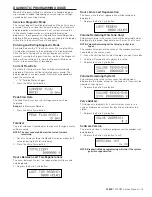


TROUBLESHOOTING
Detected Errors
NOTE: It can take up to 30 seconds for an error to be detected
and displayed. All errors on each timer in the system
must be displayed before the errors can be corrected.
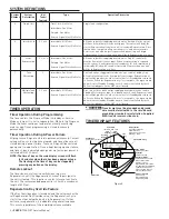
If a communication error is detected, an Error Screen will
alternate with the Main (time of day) Screen every few seconds.
• All units In Service remain in the In Service position.
• All units in Standby go to In Service.
• Any unit in Regeneration when the error occurs
completes Regeneration and goes to In Service.
• No units are allowed to start a Regeneration Cycle while
the error condition exists, unless they are manually forced
into Regeneration.
• When an error is corrected and the error no longer
displays (it may take several seconds for all of the units
in a system to stop displaying the error message), the
system returns to normal operation.
NOTE: During the error condition the control continues
to monitor the flow meter and update the volume
remaining. Once the error condition is corrected all
units return to the operating status they were in prior
to the error. Regeneration queue is rebuilt according
to the normal system operation. Or, if more than
one unit has been queued for regeneration, then the
queue is rebuilt according to which one communicates
first.
Cause For Error
Correction
One or more units have a
missing or bad communication
cable.
Connect the communication
cables and/or replace.
One or more units has a
communication cable plugged
into the wrong receptacle.
Connect the communication cable
as shown in the wiring diagrams.
One or more units is not
powered.
Power all units.
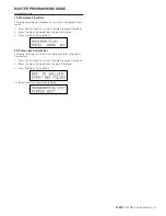
Programming Errors
During the error condition the control continues to monitor the
flow meter and update the remaining capacity. Once the error
condition is corrected all units return to the operating status
they were in prior to the error and regeneration is queued
according to the normal system operation. If reprogramming
the unit in the Master Programming Mode clears the error, the
volume remaining may be reset to the full unit capacity (i.e. as
though it were just regenerated).
• All units in Standby go In Service.
• Any unit in regeneration when the error occurs completes
regeneration and goes to In Service.
• No units are allowed to start a regeneration cycle while
the error condition exists.
When the problem is corrected and the error no longer displays
(it may take several seconds for all of the units in a system
to stop displaying the error message), the system returns to
normal operation.
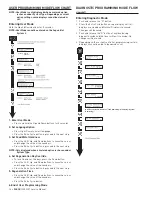
Programming Errors Detected
• Duplicate unit addresses or numbers
• Size of system ex: if sized for a 4 units, and only have 2 units
• Display format mismatches
Solution
• Program the units correctly in the Master Programming
Mode.
Cause For Error
Correction
Any or all of two or more units
programmed with the same
unit number (Matching Address
Error)
Program the units correctly in
the Master Programming Mode
Flashing/blinking display
Power outage has occurred
Format Mismatch (Units have
both U.S. and Metric Formats)
Verify all units have same Format
selected (all U.S. or all Metric)
No messages displayed/small
black squares appear in display
Turn the contrast button on the
back of unit until text appears
Size Error (Units not correctly
numbered/more than one unit
has the same number assigned)
Check each unit and verify each
as the correct number, and that
each number is used once
Com Error (Communication
Error)
Check the wiring of the system
and verify it is correct and that
all are connected
NOTE: If these errors are detected, numbers 1 through 3
become true, and the main screen (time of day) will
alternate with an error screen.
20 •
FLECK
7000 NXT Service Manual


