


6
11.
Manual pumps.
All general
instructions for automatic
pumps apply to manual pumps
except the level switch is not
used and the power cord does
not have a vent tube.
Manual models have the plug
(12) in switch cap for installing
a fitting to air test the pump for
leaks. Replace all plugs with
Permatex on threads. The
switch housing seat is tapped
and plugged with pipe plug.
Hydromatic pumps have a small
air vent hole in the impeller cavity
to let out trapped air. If this hole
becomes plugged, pump may air
lock. To break the air lock, use a
small screwdriver to clear hole in
the impeller cavity.
As a secondary precaution in
installations of this type, 1 ⁄ 16"
hole should be drilled in the
discharge pipe below the check
valve. The check valve should be
12 to 18 inches above pump
discharge. Do not put check valve
directly into pump discharge
opening.
NOTE: In sumps where the
pump is operating daily, air
locking rarely occurs.
Pump is now ready for check
run before air testing and
filling with oil. Plug cord
(21) into power receptacle and
push up on switch chamber
diaphragm (23) to start motor.
Motor should start and run
smoothly. When pressure is
released on diaphragm, motor
should stop. Repeat operation
2 to 3 times to be sure
operation is satisfactory and
not binding.
9.
Air test.
To air test unit, put air
fitting in plug opening (12) and
charge motor housing with air
to 7 psi.
Do not use higher
pressure or seal will be blown
open.
Charge switch cap with
air through nylon vent tube as
described earlier and place
complete unit under water.
No air bubbles should show on
this test. If leak shows,
unit must be dismantled to
correct leak.
10.
Oil fill.
After air test is
satisfactory, remove from
water and wipe or blow off any
excess water.
Do not put oil in motor with
any water present that could
get into motor.
Fill to 1 ⁄ 8" over motor plate
through opening. Use oil fill
tube that will go into holes so
that air can escape. Replace
plug (12) and pump is ready
for operation. Use only high
grade transformer oil or special
Hydromatic submersible oil in
motor.
Pump
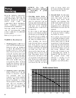
Servicing
Performance Curve
Summary of Contents for HYDROMATIC SP50
Page 3: ...3 Pump Installation ...


