


5
back slowly. If it does not, the
capacitor should be replaced.
6. To check motor stator, remove
power cord leads from terminal
bushings on top of motor. If
stator is visibly burned, motor
assembly must be replaced.
7.
Ground check
on stator
should be performed using
ohmmeter with scale set at R X
100 and checking meter by
putting both meter leads
together and adjusting the needle
knob until meter reads zero. If
meter cannot be adjusted to
zero, it will indicate that
batteries in meter must be
replaced. Always make this
test with the meter when scale
pointer is set to a new scale
before making any checks on
the motor.
Now connect one meter lead to
one terminal of stator and
touch and other meter lead to
motor stator shell. If needle on
ohmmeter goes completely to
zero, the motor probably has a
wire touching the stator at
some point and the motor
assembly will have to
be replaced.
8.
Winding Resistance Test:
should be performed if the
ground test is satisfactory. Use
ohmmeter with scale pointer
set on R X 1 scale. On this
scale, meter reads directly on
ohms. Always check the meter
with leads together as
described above under Ground
Check Test before making a
reading of the winding.
Connect one motor lead to the
white wire terminal and the
other meter lead to the black
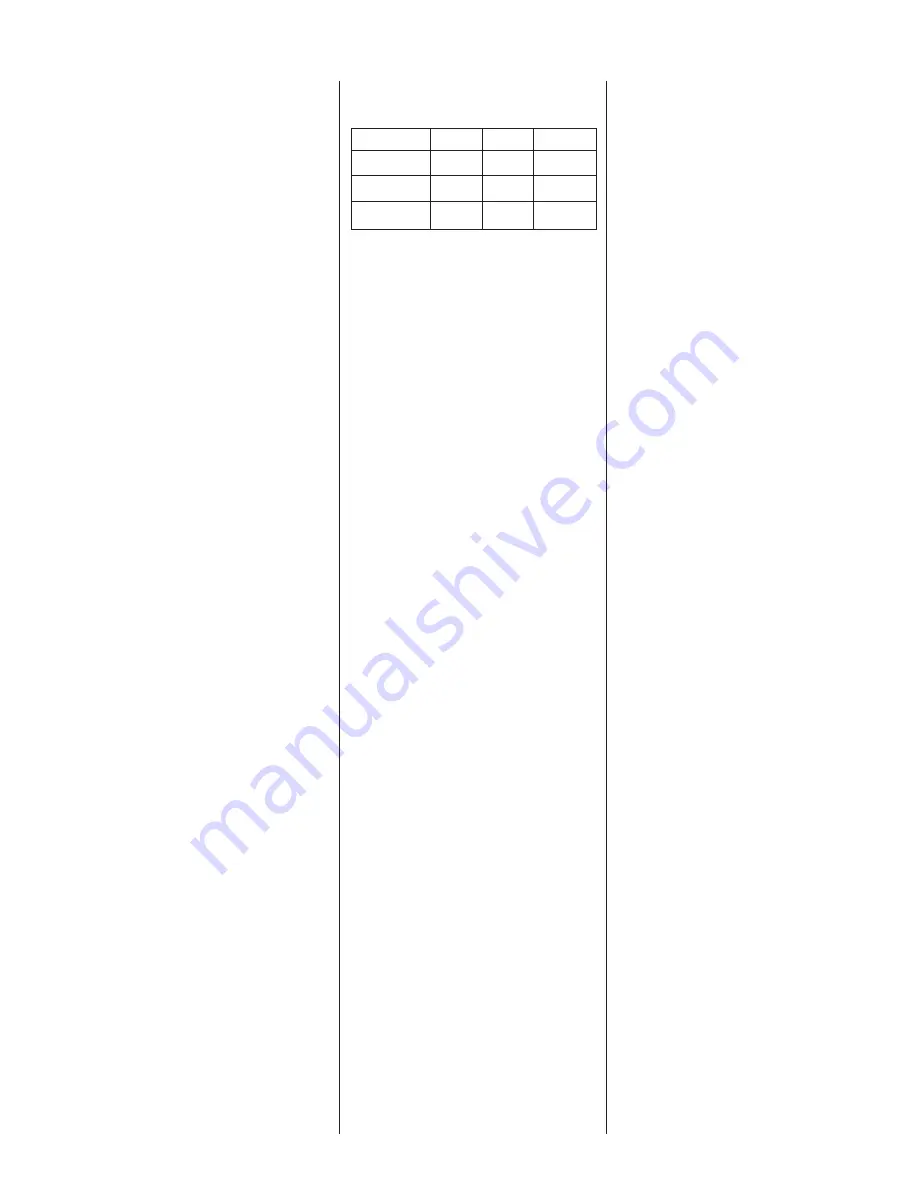
wire terminal. This reading is
for the main winding (1ø). If
the readings obtained do not
agree with those given below,
the stator is defective and the
motor assembly must be replaced.
Resistance:
1ø Main1ø Start3ø Bal.
230V
1.78
3.53
6.65
460V
—
—
6.65
200V
—
—
3.4
575V
—
—
27.97
9. For three phase pumps,
remove the power cord assembly
(#27) by cutting the butt
connections and removing the
power cord from the pump.
10.Twist the three leads of one
end of the power cord together.
Then at the other end, with an
ohmmeter, check any two
leads. Also check the third lead
with either of the first two. If a
zero reading is indicated for
any wire, the wire is broken
and a new power cord assembly
must be installed.
Seal Housing:
The pump is equipped with two
mechanical seals mounted in
tandem. The lower seal (#20) and
the upper seal (#8) consist of a
ceramic stationary seat and a
carbon rotating ring.
As noted, if water is detected in
the motor housing, inspect the
power cord connection, pipe plug
connections, O-rings, the motor
housing itself, and the two
mechanical seals.
There are two quarts of oil in the
motor housing. This is a paraffinic
“SE-40” process oil. The same oil
is used in the seal housing (#13)
between the two mechanical seals.
To check the seals, remove the
lower housing pipe plug (#11)
and pour the oil out into a
clean, preferably glass, container.
Look for the milky color as
noted previously.
If the oil is clear, the lower seal is
still good. If this seal is damaged,
water will seep in and continue to
stain the oil, changing it
from clear, to slightly discolored,
to cloudy, and finally to a
milky white.
Except for very rare instances, the
motor will continue to be protected
by the upper mechanical seal. If
seal probe is used the pump will
not shut off when water in the oil
is sensed. However, if connected
to a control panel, an alarm
or light will be activated. The
panel alarm will show failure.
The lower seal and oil must
be replaced.
Lower Seal:
If water is found in the seal
chamber, the lower seal must be
replaced. Separate the volute by
removing the three cap screws
(#7) holding the volute case (#10)
to the upper volute.
Insert a large screwdriver in the
slotted pump shaft and strike the
impeller sharply with a plastic or
rubber headed hammer. The
impeller should spin free. The
impeller holds the rotation carbon
ring of the lower mechanical seal
against the stationary ceramic
seat by compressing a stainless
steel spring.
When the impeller is removed, the
spring will relax, allowing the
carbon ring to be removed. There
is a rubber sleeve (bellows) inside
the spring which grips the pump
shaft. This often restricts the
spring and must be pried or
pulled loose.
With the carbon ring, spring, and
rubber sleeve removed, wedge the
ceramic seat out of the housing.
Be sure not to scratch or mar the
pump shaft.
Upper Seal:
1. To remove and replace the
upper mechanical seal (#8), the


