background image

23

Do not turn your system on immediately.

 The system can be operated 

only after the mortar or self-leveling underlayment has completely cured.

This  waiting  period  is  essential  to  ensure  that  the  mortar  or  self-leveling 
underlayment is properly set. Refer to manufacturer’s instructions to verify the 
curing time for the product you are using (generally 28 days).

After 

fl

ooring is installed,

 turn the system on brie

fl

y to test its operation. 

Do not run the system for more than a few minutes before the mortar has 

fi

nished curing. 

When  setting  a  temperature,

  be  sure  to  check  the  thermal  limits  of 

your  chosen 

fl

oor  covering.  Wood  and  laminate 

fl

oorings  often  have  a 

recommended maximum of 29°C (84°F) . 

Do not exceed this value. 

Activating the system.

 Depending on the 

fl

oor covering and temperature 

of the room, it can take some time for the system to warm up. Carefully pull 
the heating leads from the wall and check them using a clamp-style ammeter. 
Con

fi

rm that the system is drawing current.

Make sure the system is turned off after a maximum of 10 minutes.


Do  not  re-activate  the  system  until  the  required  time  has  passed  for  the 

fl

oor mortar to completely cure. Once this curing is 

fi

nished, the system is 

complete!

>

>

>

>

>

>

07 System Start-Up

Summary of Contents for Warmset

Page 1: ...Installation Manual Warmset Floor heating system Warmset Ltd ...

Page 2: ...al building codes and regulations may require all or part of the installation of this product and or the corresponding thermostat to be performed by a licensed electrician Leave this manual with the end user ...

Page 3: ...nal Electrical Code US ANSI NFPA 70 and Section 62 of Canadian Electrical Code CEC Part 1 Product Information Specifications Mesh Mat Attention Installation 01 Before Beginning 02 Installation Preparations 03 Electrical Rough in 04 Mat Installation 05 Thermostat Installation 06 Floor Coverings 07 System Start Up Troubleshooting System information System Information table Mat Data sheet 3 9 25 27 2...

Page 4: ...cal wiring is required Although Warmset products may be installed by any qualified person pending local codes it is recommended that a certified and licensed electrician roughs in the power supply wiring Please check and adhere to all local codes as they may require all or part of the installation to be performed by a licensed electrician With electric radiant floor heating performance is never gu...

Page 5: ...120 240 VAC Power 120 W m2 11 1 W ft2 Max circuit load 15 A Max circuit overload protection 20 A breaker Mat length 1 40 m 3 131 ft Mat width 0 5 m 20 in Thermostat Warmset Mats must be controlled by a floor sensing thermostat ...

Page 6: ...5 Mesh Mat E B C C C A D A Fiberglass mesh B Heating ribbon C Double sided tape D Factory splice E Power lead F Factory end F ...

Page 7: ...Latex Latex Modified Thinset C Probe D Warmset E Plywood floor A Tile Stone Resilient Flooring B Latex Modified Thinset Flooring Glue C Self Leveling compound D Probe E Warmset F Insulated Board G Concrete Floor Tile Stone Resilient Flooring with Plywood subfloor Tile Stone no self leveling compound with Plywood subfloor Tile Stone Resilient Flooring with Concrete Subfloor G E G F D F E C E D C B ...

Page 8: ...g grout lines with sharp tools or power tools may damage the heating ribbon and will void the Warmset Warranty Never cut the heating ribbon If the heating ribbon is cut it can cause electric shock dangerous over heating or fire If necessary the cold leads may be cut shorter but never remove them completely from the heating ribbon Never use metal penetrative fasteners such as nails staples or screw...

Page 9: ...ar Always adhere to all power limitations of the breaker thermostat and chosen Warmset Mat Be sure the Voltage and Current are appropriate for the system Always install Warmset mats on a dedicated 20 A circuit Always make sure all electrical work is done by qualified people in accordance with local electrical and building codes Always use copper wiring to complete the connections in the Warmset sy...

Page 10: ...ll not radiate well beyond roughly 1 1 2 on either side of the heating ribbon To avoid cold spots consistent coverage is important Heating ribbon must not be installed within 2 of a built in such as a counter or vanity Be sure not to install heating ribbon underneath cabinets or furniture with no floor clearance Excessive heat build up can cause damage Do not place the heating ribbon within 4 of o...

Page 11: ...er a variety of subfloors Make sure that your chosen subfloor is compatible with cement adhesives Common subfloor materials are plywood existing tiles cement various insulations and concrete slabs When selecting multiple mats pay close attention to the total current load Try to design your system so that it does not exceed 80 of the rated current of the breaker Use a Warmset thermostat or equivale...

Page 12: ...ders tape All necessary small hand tools drills screwdrivers measuring tape marker shears to cut mesh substrate etc The installer must be familiar with electrical wiring techniques and any relevant local building codes A licensed electrician is recommended If applicable the installer should also be familiar with the appropriate floor covering techniques Unpack and inspect all components of the pla...

Page 13: ... value it might be due to low air tem perature or meter calibration Contact Warmset if in doubt The system should also be checked for short circuits Measure the white or red for 240 VAC lead to ground green and yellow and black lead to ground Both of these measurements should read no continuity Some meters display this as infinite ohms or open line These steps are performed three times in the inst...

Page 14: ...dryers pull 1200 watts of load and some can draw more Choose a location and install an electrical box for the thermostat Use an extra deep electrical box For installations with several mats a larger box may be required Electrical boxes should be located in a well ventilated area and placed so that the leads from any mats or junction boxes can easily reach it It must also be able to connect back to...

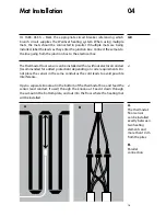
Page 15: ...acles or unusual room shapes the heating element may be removed from the mesh When the heating ribbon is removed from the mesh to facilitate working around obstacles or unusually shaped rooms the measured center to center spacing between runs must be maintained throughout the installation However in order to maintain even heat dissipation avoid removing excessive amounts of mesh Depending on your ...

Page 16: ...15 04 Mat Installation A Cut the mesh on the dotted line B Be careful to not damage the heating element A B ...

Page 17: ...6 04 Mat Installation C Once the mesh has been cut the element can be unfolded to the desired angle D The mats can be cut for several angles allowing the system to work around almost any obstacles C C D ...

Page 18: ...le This will help make a smooth surface for spreading mortar Do not completely cover the heating ribbon with tape Once the entire system has been fitted and secured test the resistance of the system as outlined in part 2 3 and note it in the table located on page 28 Connect the leads from the heating mats back to the electrical box or junction box The cold leads can be installed with or without el...

Page 19: ... with or without electrical conduit recommended for added protection depending on code requirements Do not place the sensor in the same conduit as the cold leads to avoid possible interference Open a separate knockout in the bottom of the thermostat box and feed the sensor and conduit if used through the knock out Feed it down through the cut out in the bottom plate and out into the floor where th...

Page 20: ...r cable must pass outside the electrical box and follow the wall down to the floor Position the sensor cable such that it does not come in contact with the floor heating wires The sensor must be centered between two floor heating ribbons for best temperature control Do not staple the sensor head the plastic end to the floor Doing so might damage the sensor Any damage might not be noticeable during...

Page 21: ...duit E Sensor Wire F Mat Cold Lead G Sensor Installed in Floor equal distance between two heating wires and 1 foot from the wall H Warmset Mat I Thin set thick set thin slab or self leveling mortar bed L Tile Stone or Laminate Floor Covering 05 Thermostat Installation A I H G L E C F D B ...

Page 22: ...e temperature to 84 degrees F 28º Celsius Vinyl flooring materials can also have similar temperature restrictions Some carpets or rugs can be laid over a heated floor but they act as insulators and will reduce heat flow to the room Check with the carpet manufactuerer to confirm if the carpet is safe for heated floors Remember to obtain maximum effectiveness of Warmset mat systems the combined R va...

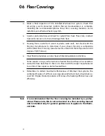
Page 23: ...e manufacturer s recommendations Ensure the Warmset mat is first covered with a layer of self leveling cement based mortar allowing it cure fully before applying any surface underlayment or other flooring materials Self leveling compounds can be appropriate if installing ceramic or stone tile engineered wood vinyl laminate or carpet floor coverings Attach the Warmsetmattothesubfloororslab andthenp...

Page 24: ...inished curing When setting a temperature be sure to check the thermal limits of your chosen floor covering Wood and laminate floorings often have a recommended maximum of 29 C 84 F Do not exceed this value Activating the system Depending on the floor covering and temperature of the room it can take some time for the system to warm up Carefully pull the heating leads from the wall and check them u...

Page 25: ... Please refer to the warranty card included with this document for complete details Complete and return the warranty card in order to preserve system waranty Ensure to record resistance and insulation verrification test results and all other information requested on the warranty card ...

Page 26: ...lectric devices including electric motors can create interference for GFCIs creating false trips If the Warmset mat system shares a circuit breaker with any other devices move the system to its own breaker If the breaker trips again after these steps replace the GFCI If a thick stone or concrete floor covering is installed the system might take an extended period of time to heat the surface Ensure...

Page 27: ...manual for your thermostat Double check that you followed all programing instrucitons Probable issue if the thermostat is displaying HI or a high and even value such as 50 C or 100 F Double check floor sensor wiring Contact Manufactuerer Check the power being sent to all components of the system Make sure all values are as expected Check all system wiring Check that the thermostat was not left out...

Page 28: ...system contains more than 4 mats the following data and measurements should be recorded for the additional mats This page can be photocopied or additional information tables can be sketched Please attach any additional pages to this package before giving it to the homeowner Keep this installation log System information ...

Page 29: ...esistance measurements Once concrete has been poured Resistance measurements White 240 Vac Red to black White 240 Vac Red to Ground Black to Ground White 240 Vac Red to black White 240 Vac Red to Ground Black to Ground White 240 Vac Red to black White 240 Vac Red to Ground Black to Ground System information ...

Page 30: ... 90 8 2 54 16 5 990 2 9 8 25 14 5 13 9 16 2 WS 120 90 100 9 1 60 18 3 1110 4 7 9 25 13 0 12 4 14 4 WS 120 100 Rated Voltage 120 VAC Power Class 11 1 W ft2 120 W m2 Current Differential When designing a project using Warmset by Penrod special attention is need ed when connecting multiple mats or large single mats in a wet area Class A thermostats have GFCI protection and will trip when the cd curre...

Page 31: ... 1115 4 4 6 51 7 49 2 57 4 WS 240 100 105 9 6 63 19 2 1170 4 4 9 49 2 46 9 54 7 WS 240 105 110 10 2 67 20 1221 3 8 5 1 47 2 44 9 52 4 WS 240 110 115 10 5 69 21 1282 4 3 5 3 44 9 42 8 49 9 WS 240 115 120 11 1 73 22 1332 4 9 5 6 43 2 41 2 48 WS 240 120 125 11 4 75 22 9 1393 5 5 8 41 3 39 4 45 9 WS 240 125 130 12 0 79 24 1443 5 6 0 39 9 38 44 4 WS 240 130 135 12 3 81 24 7 1505 5 1 6 3 38 3 36 5 42 5 ...

Page 32: ...d Company Virginia Beach Virginia www thepenrodcompany com Warmset Floor Heating Systems Toll Free 1 800 537 3497 technical thepenrodcompany com Warmset Ltd Cambridge Ontario 2013 Warmset Ltd All rights reserved ...

Reviews: