


2.0 INSTALLATION
2.2 Installation preparation
Consideration must be taken in relation to the appliance location and safe flue route in the first instance in accordance with
the appliance instructions and technical data. The chimney must be suitable for operating the appliance safely and all selected
components must be compliant in accordance to the relevant British standards.
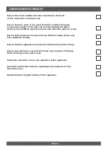
The appliance and flue system must be installed by a HETAS registered engineer and pertinent commissioning documents and
evidenced system checks of the installation in its entirety must be left with the end user.
Location
Choose a location for the appliance close to the chimney to prevent the use of a long horizontal connecting pipe. All horizontal
rear connections must not be more than 150mm.
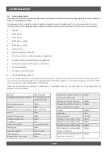
The location of appliance must be flat and level. The floor must also have the necessary load bearing capacity. The weight of
the appliance can be found on the attached technical data. In case the load-bearing capacity of the floor is too low, usage of a
plate for better load distribution might help, but a structural engineer must advise if in any doubt.
Fixing Ceramic Glass or Soapstone Lid
Before connecting the stove, please take off all accessories that are not attached, such as top soapstone/ceramic tile or the
soapstone /ceramic tiles placed in the warming plate. This way you can prevent these parts from falling while moving the
stove. Do not attempt to maneuver the stove in to position or work on the flue with the soapstone or ceramic top in place as it
may become damaged. For further information to retrofit any soap stone covers then the manufacturer must be contacted in
the first instance.
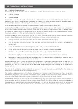
2.3 Ventilation
Ventilation must be provided in accordance with Approved Document J .If the appliance is to be installed in to a room which is
completely airtight, a separate external air inlet pipe is needed to guarantee a sufficient supply of air for the safe operation of
the appliance. The appliance may have an optional connection for the use of an external direct air supply and for guidance on
installation, please see the Percy Doughty Technical Bulletin #002.
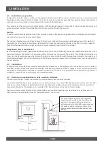
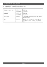
2.4 Distance to combustibles or heat sensitive materials
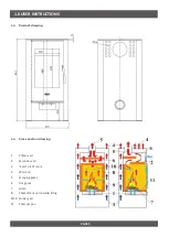
The technical data Fig 2.1 shows the distances to combustible and heat sensitive materials.
In case of combustible floors, being sensitive to a rise in temperature, non-combustible floor protector must be used. This floor
protector must reach 500mm beyond the front (from the charcoal pan), 300mm beyond the side (from the inner wall of the
combustion chamber) of the appliance. The material of the floor protector can be made of metal or glass.
The given minimum safety distances from combustible or heat sensitive materials must be adhered to at all times and not
compromised, this will include all areas of the appliance front, rear & sides.
PAGE 8
The connecting flue pipe must be of single wall
construction and must fit inside the collar on the
appliance – the connecting flue pipe must be a
minimum vertical length of 600 mm directly above
the top flue outlet to create laminar flow of the
exhaust gases and reduce the deposition of soot
and tar.


