ECP 200 BASE 2 / 4
USE AND MAINTENANCE MANUAL
REV. 01-09
Page 1: ...ECP 200 BASE 2 4 USE AND MAINTENANCE MANUAL REV 01 09...
Page 2: ...ECP200 BASE 2 4...
Page 3: ...ECP200 BASE electronic controller Page 18 5 12 Compressor activation deactivation conditions Page 18 5 13 Manual defrosting Page 19 5 14 Hot gas defrosting Page 19 5 15 Pump down function Page 19 5 1...
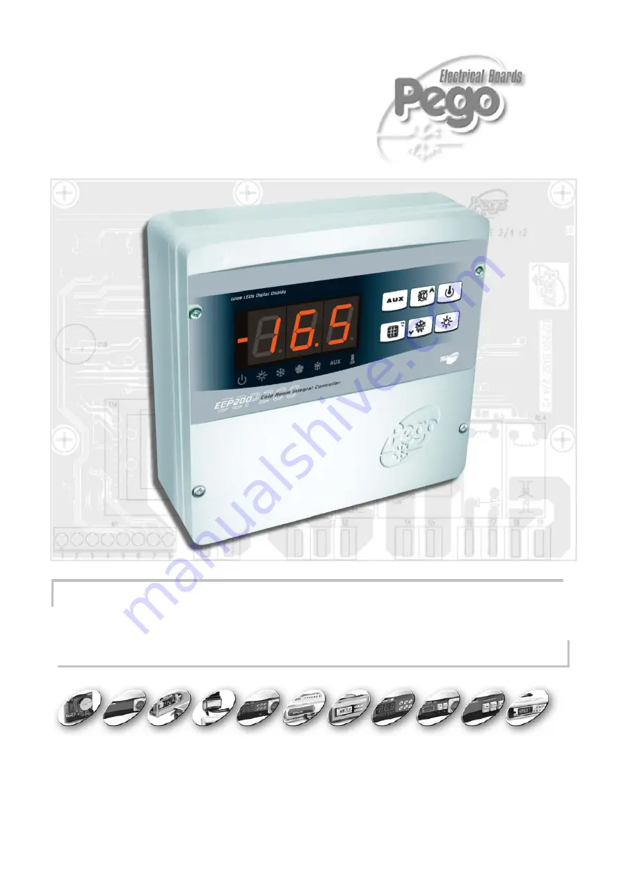
Page 4: ...ote condensing unit consensus The ECP200 BASE 2 electronic board allows the user to control the compressor and room light The applications are single phase refrigeration systems up to 2 HP with off cy...
Page 5: ...ENSIONS IDENTIFICATION DATA The unit described in this manual has an ID plate on the side showing all the relevant identification data Name of Manufacturer Code and model of unit electrical board Seri...
Page 6: ...he same raceways or ducts 4 Minimise the length of connector wires so that wiring does not twist into a spiral shape as this could have negative effects on the electronics 5 Fit a general protection f...
Page 7: ...pecially careful to keep power wires away from signal wires Use clips to hold wires in place Fig 3 close the front panel making sure that all the wires are inside the box and that the box seal sits in...
Page 8: ...om parameter System control activation deactivation System warnings probe sensor errors minimum and maximum temperature warnings compressor shutdown Evaporator fans control Automatic and manual defros...
Page 9: ...plicable load 230 V AC Compressor 1500 W AC3 Elements 3000 W AC1 Fans 500 W AC3 Room light 800 W AC1 Alarm contact non powered contact 100 W BASE 4 A version only ECP200 BASE 2 Output characteristics...
Page 10: ...ING Any modifications made to wiring and or internal components or any work carried out in a way that fails to comply with the information instructions in this manual shall render the warranty null an...
Page 11: ...on the version with alarm relay controls the relay manual if parameter AU 1 2 key UP MUTE WARNING BUZZER 3 key STAND BY if the system shuts down the LED flashes 4 key room temperature SETTING 5 key D...
Page 12: ...1 Cold room temperature parameters 2 Stand by flashes on stand by Outputs are deactivated 3 Room light flashes if door switch activated 4 Cold indicates activation of compressor 5 Fans 6 Defrosting 7...
Page 13: ...Level 2 programming directly from Level 1 you must exit the programming mode first KEY TO SYMBOLS For purposes of practicality the following symbols are used t the UP key is used to increase values an...
Page 14: ...and u keys 3 Select the variable to be modified using the t or u key 4 When the variable has been selected it is possible to display the setting by pressing SET key to modify the setting by pressing t...
Page 15: ...ter defrost minutes Allows fans to be kept at standstill for a time F5 after dripping This time begins at the end of dripping If no dripping has been set the fan pause starts directly at the end of de...
Page 16: ...LEVEL 2 VARIABLES Installer level VARIABLES MEANING VALUES DEFAULT AC Door switch status 0 normally open 1 normally closed 0 F3 Fan status with compressor off 0 Fans run continuously 1 Fans only run...
Page 17: ...ntrolled via AUX key 2 automatic auxiliary relay managed by StA temp setting with 2 C differential 3 relay disabled TeleNET function 4 pump down function see 5 15 5 free voltage contact for condensing...
Page 18: ...troller activates the compressor when cold room temperature exceeds setting differential r0 it deactivates the compressor when cold room temperature is lower than the setting MANUAL DEFROSTING To defr...
Page 19: ...y control PUMP DOWN FUNCTION Pump down function is activated when parameter AU 4 only for version with AUX Alarm relay Connect pump down pressostat on the digital input 1 3 The compressor is directly...
Page 20: ...PERVISION SYSTEM For connections regarding the TeleNET monitoring supervision system see APPENDIX A 10 page 32 of this manual and for the ECP200 BASE4A and ECP200 BASE2A models jumper JP2 as described...
Page 21: ...on the front panel Fig 3 Undo the 6 CPU board fixing screws and remove the board from the frontal section of the box in ABS Fig 4 Remove the jumper from JUMPER JP2 Fig 5 Insert the jumper in JUMPER JP...
Page 22: ...alarm An EEPROM memory alarm has been detected All outputs except the alarm one are deactivated Switch unit off and back on E8 Man in cold room alarm Reset the alarm input inside the cold room Ec Comp...
Page 23: ...s relating to electrical equipment employed within certain voltage limits and subsequent amendments 89 336 CEE Direttiva del Consiglio per l unificazione delle normative dei Paesi CEE relativa alla co...
Page 24: ...ECP200 BASE 2 4 Page 24 USE AND MAINTENANCE MANUAL Rev 01 09 ECP200 BASE4 WIRING DIAGRAM A 2 Allegati Appendices...
Page 25: ...ECP200 BASE 2 4 Page 25 USE AND MAINTENANCE MANUAL Rev 01 09 ECP200 BASE4A WIRING DIAGRAM A 3 Allegati Appendices Opzionale Vedi capitolo opzioni...
Page 26: ...ECP200 BASE 2 4 Page 26 USE AND MAINTENANCE MANUAL Rev 01 09 ECP200 BASE2 WIRING DIAGRAM A 4 Allegati Appendices...
Page 27: ...ECP200 BASE 2 4 Page 27 USE AND MAINTENANCE MANUAL Rev 01 09 ECP200 BASE2A WIRING DIAGRAM A 5 Allegati Appendices Opzionale Vedi capitolo opzioni...
Page 28: ...ECP200 BASE 2 4 Page 28 USE AND MAINTENANCE MANUAL Rev 01 09 CONNECTION EXAMPLE 1 ECP200 BASE4 BASE4A Connection with outputs powered for direct control of functions A 6 Allegati Appendices...
Page 29: ...NTENANCE MANUAL Rev 01 09 CONNECTION EXAMPLE 2 ECP200 BASE4 BASE4A Mixed connection with on off contact to enable towards condensing unit power board and fan light and defrost outputs powered for dire...
Page 30: ...ECP200 BASE 2 4 Page 30 USE AND MAINTENANCE MANUAL Rev 01 09 CONNECTION EXAMPLE 3 ECP200 BASE2 BASE2A Connection with outputs powered for direct control of functions A 8 Allegati Appendices...
Page 31: ...SE AND MAINTENANCE MANUAL Rev 01 09 CONNECTION EXAMPLE 4 ECP200 BASE2 BASE2A Mixed connection with on off contact powered to enable towards room power board and light output powered for direct control...
Page 32: ...TeleNET NETWORK CONNECTION WIRING DIAGRAM BEFORE CONNECTING UP COMMUTATE THE DATAPRINTER PLUS PRINTER TeleNET FUNCTION VIA DIP SWITCH AS INDICATED IN CHAP 6 PAGE 23 Allegati Appendices A 10 Morsettie...
Page 33: ...ts powered for direct control of functions Allegati Appendices A 11 Power supply 230Vac 50Hz Outputs powered for direct control of functions Digital input and probe connections SCHINT230 optional kit...
Page 34: ...ECP200 BASE 2 4 Page 34 USE AND MAINTENANCE MANUAL Rev 01 09 SCHINT230 OPTIONAL KIT WIRING DIAGRAM A 12 Allegati Appendices Allegati Appendices...
Page 35: ...ECP200 BASE 2 4 Page 35 USE AND MAINTENANCE MANUAL Rev 01 09 NOTE...
Page 36: ...ECP200 BASE 2 4 Page 36 USE AND MAINTENANCE MANUAL Rev 01 09 PEGO S r l Via Piacentina 6 b 45030 OCCHIOBELLO ROVIGO Tel 0425 762906 Fax 0425 762905 www pego it e mail info pego it Distributor...