PeerlessBoilers Gas/Oil Boilers Installation & Maintenance Manual Download Page 6

4

8. Exterior Vents:

a) Insulate sufficiently to ensure adequate draft and

to prevent vent damage due to condensation.

9. Vent Connection to Boiler:

a) Support the weight of the vent system

independently of the boiler flue connection.

b) Provide support of the vent connector

(breeching) at maximum 12 foot intervals to
prevent sagging and to provide a minimum
upward slope of 1/4" per foot.

10. Do not vent natural draft appliances in a combined

vent which operates under positive pressure.

11. Draft Regulator: Install a barometric draft regulator

where using high chimney or any high draft vent.
This is needed to prevent causing negative draft in
the boiler. Excess draft will cause flame lifting and
possible impingement.

12. The Draft Damper for the LCE boiler is a separate

piece, shipped in the Top Flue Outlet Carton.

a) Install the Draft Damper as close as possible to

the boiler flue outlet. It can be installed vertically
or horizontally provided that the connecting vent
piping and fittings are designed and installed for
pressurized service.

b) Secure the damper to the vent with screws and

seal the joints with a bead of high temperature
silicone sealant (found in Section Assembly Kits).

c) The vent must be installed so it can be

disconnected and the Top Flue Outlet removed
for proper cleaning of the flueways.
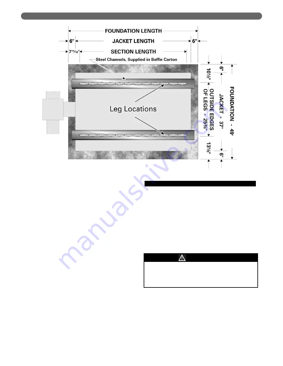
E. BOILER SETTING

1. If the boiler room floor is not level or if additional

structural support is needed, provide a good, level
foundation for the boiler with the minimum
dimensions given in Table 1.1. The flooring and
structural support system must be suitable for the
operating weight of the boiler and any connected
piping. Place the Steel Channels on the foundation
as shown in Figure 1.4.

2. Do not operate the boiler until the foundation, if new

concrete, has thoroughly cured. The concrete might
be damaged if heated too quickly due to the
entrained moisture remaining.

3. If the boiler is installed in a penthouse or if wiring of

any sort is run underneath the boiler foundation,
construct the foundation with provision for air flow
underneath between the main floor and the top of
the boiler foundation.

a) An acceptable foundation would be concrete

blocks laid with the openings lined up.

Do not install this boiler on carpeting or any
combustible flooring. A significant fire hazard could
result, with potential for property damage, personal
injury or death.

WARNING

Figure 1.4: Foundation Layout

PREINSTALLATION

Summary of Contents for Gas/Oil Boilers

Page 1: ...LC LCE Gas Oil Boilers Water Series Oil Gas Installation Operation Maintenance Manual...

Page 2: ...SIDES AND CORNERS 27 C APPLY JACKET FRONT PANELS 27 D APPLY JACKET REAR PANEL 27 E APPLY JACKET TOP PANELS 27 F APPLY PLATES AND LABELS 27 5 VENTING 29 6 INSTALL THE BURNER 29 A BURNER APPLICATION 29...

Page 3: ...pecial notice of potential hazards These categories mean in the judgment of PB Heat LLC Indicates special attention is needed but not directly related to potential personal injury or property damage N...

Page 4: ...of tankless heaters provide 45 between the end of the boiler and any adjacent wall of obstruction This provides for all available tankless coils The spacing can be closer for Heater Number X 1020 all...

Page 5: ...ect chimney liner and repair or replace if necessary 2 The vent system and installation must be in accordance with the current edition of the American National Standard ANSI NFPA 211 Chimneys Fireplac...

Page 6: ...a bead of high temperature silicone sealant found in Section Assembly Kits c The vent must be installed so it can be disconnected and the Top Flue Outlet removed for proper cleaning of the flueways E...

Page 7: ...pment such as barometric draft dampers may also be shipped separately 2 Knockdown All components shipped for field assembly See Table 1 2 for standard components See Tables 1 3 through 1 8 for optiona...

Page 8: ...1 LC 1000 1 86005 1 LC 1000 1 86005 1 LC 1000 1 86005 1 LC 1000 1 86005 1 LC 1000 1 86005 1 LC 1000 1 86005 1 LC 1000 1 86005 1 LC 1003 86008 1 LC 1003 86008 1 LC 1003 86008 1 LC 1003 86008 1 LC 1003...

Page 9: ...LC 1000 86004 1 LC 1007 86022 1 LC 1007 86022 1 LC 1007 86022 1 LC 1007 86022 1 LC 1007 86022 1 LC 1007 86022 1 LC 1007 86022 1 LC 1007 86022 1 LC 1007 86022 1 LC 1007 86022 1 LC 1007 86022 1 LC 1007...

Page 10: ...C 1015 1 LC 1016 2 LC 1017 2 86012 86015 86112 86093 86017 86020 86028 Table 1 6A Burner Mounting Plates Model CF 800 CF 1400 CF 2300 301CRD 702CRD 801CRD S4 2 R6 2 R6 3 R8 1 R8 2 R8 3 C1 C2 J15A J30A...

Page 11: ...lief Valve selection based on capacity determined by boiler output Gross I B R Output Applies to most locations in United States and Canada Table 1 6B Burner Mounting Plates Model CF2300AKG CF2300AKB...

Page 12: ...allation 2 Remove lifting frame and hardware 3 Proceed to Section D Install Coils or Plates C KNOCKDOWN BOILER 1 Place channel rails as shown in Figure 1 4 2 Open the Section Assembly Kit cartons Thes...

Page 13: ...0 Lift up the Rear Section and move into position on the steel channels on the boiler foundation 11 Screw a 3 pipe at least 30 inches long into the lower 3 tapping on the back of the Rear Section as s...

Page 14: ...12 PLACE THE BOILER Figure 2 4 Install Additional Sections Use level on each section as tie rod bolts are drawn up...

Page 15: ...13 PLACE THE BOILER Figure 2 5 Series LC Boiler Assembly Right Side View...

Page 16: ...14 PLACE THE BOILER Figure 2 6 Series LCE Boiler Assembly Right Side View...

Page 17: ...grating into the boiler room 17 Repeat with the remaining sections a Save the LWCO Intermediate with two 1 tappings for level control for use as the section closest to the front section b Place the In...

Page 18: ...16 Figure 2 9 LC LCE Boiler Section Assembly Sequence PLACE THE BOILER...

Page 19: ...LC 11 LC 12 LCE 13 LCE 14 LCE 15 LCE 16 LCE 17 LCE 18 LCE 19 LCE 20 LCE 21 LCE 22 LCE 23 LCE 24 Model GPM Location 5 5 5 62 5 75 6 25 6 5 7 0 7 25 7 5 8 0 2 2 2 2 2 2 2 2 2 GPM Location 6 5 7 0 7 75 8...

Page 20: ...12 LCE Attach the Rear Flue Cover Plate to the Rear Section with 5 16 x 1 1 2 studs flat washers and nuts supplied 3 LCE Apply spray adhesive supplied in Section Assembly Kits to the rope groove on t...

Page 21: ...ith a 1 4 hole punched in each end These baffles must be placed in the lowest row of tubes 4 Install the Front Cleanout Plate I INSTALL CHAMBER LINER 1 LCE Remove Ceramic Fiber Liner from Jacket Carto...

Page 22: ...Lower flow rates higher temperature rise are acceptable provided the return temperature to the boiler is at least 130 F on gas boilers and 150 F on oil boilers to prevent condensation of flue gases 3...

Page 23: ...04 3777 I B R Gross Output MBH 55 65 71 87 103 119 135 151 167 183 197 213 228 244 260 276 292 308 326 343 360 378 GPM 20 F Rise 1 1 1 1 1 2 2 2 2 2 2 2 2 2 2 2 2 2 2 2 2 2 Suggested Supply Connection...

Page 24: ...is piping will not work for variable low temperature systems such as outdoor reset systems or primary secondary systems with a large primary circuit temperature drop See Figure 3 4 for multiple boiler...

Page 25: ...ch boiler should be provided with its own pump and piped off of the secondary loop header See Figure 3 7 for systems with return temperature above 130 F on gas boilers or 150 F on oil boilers For low...

Page 26: ...24 Figure 3 6 Piping for Variable Low Temperature Systems Single Boiler PIPE THE BOILER...

Page 27: ...25 Figure 3 7 Multiple Boiler Piping System Return Temperature Above 130 F on Gas 150 F on Oil PIPE THE BOILER...

Page 28: ...26 Figure 3 8 Piping for Variable Low Temperature Systems Multiple Boilers PIPE THE BOILER...

Page 29: ...panels pushed up against the front section You will need the jacket in this position to install the Burner Front Plate D APPLY JACKET REAR PANEL 1 Attach the Rear Jacket Panel to the Jacket Side Pane...

Page 30: ...28 ASSEMBLE THE JACKET Figure 4 2 Jacket Assembly...

Page 31: ...nsertion length and near tube configuration Make sure the front plate is correct for your burner if purchased separately from the boiler 2 Remove the Burner Mounting Plate and Hardware Bag from the cr...

Page 32: ...E 21 LCE 22 LCE 23 LCE 24 Model Chamber Length A Inches Burner Front Plate Extension Past Jacket Inches Beckett Carlin Gordon Piatt Power Flame Webster 18 23 23 29 34 39 44 49 54 59 64 69 74 79 84 89...

Page 33: ...il flow should the oil line break C INSTALL GAS SUPPLY PIPING 1 Size the piping as required by the National Fuel Gas Code ANSI Z223 1 or as required by local codes a Use Table 7 1 for sizing of natura...

Page 34: ...4700 4100 3600 3250 3000 2600 2500 2000 17500 12000 9700 8300 7400 6800 6200 5400 5100 4100 44000 31000 25000 22000 20000 18000 17000 15000 14000 11500 Pipe Length Feet 1 1 4 Pipe 1 1 2 Pipe 2 Pipe 2...

Page 35: ...gs for mounting a float type control D INSTALL CONTROLS TRIM 1 Install the Temperature Pressure Gage in the 1 2 tapping at the upper center of the Front Section See Figure 8 2 2 Mount the Operating Te...

Page 36: ...plied with the burner and the boiler G INSTALL CONTROL WIRING 1 Wire the boiler according to the wiring diagrams supplied with the burner and the boiler in the Boiler Envelope 2 Low Energy Safety Cont...

Page 37: ...35 INSTALL CONTROLS AND TRIM Figure 8 2 Control and Pipe Tapping Locations...

Page 38: ...36 INSTALL CONTROLS AND TRIM Figure 8 4 Suggested Piping Dual Tankless Coil Installation Figure 8 3 Suggested Piping Single Tankless Coil Installation...

Page 39: ...he minimum temperature of potential exposure for the system when deciding on the antifreeze concentration A concentration of 50 generally provides protection from freezing down to 30 F 2 Purge the air...

Page 40: ...nction correctly 5 After all controls have been proven set the Operating and High Limit Temperature Controls to the temperatures desired 38 STARTING THE BOILER Table 9 1 Typical Combustion Chamber Pre...

Page 41: ...ovide adequate ventilation Wear a NIOSH MSHA approved respirator Wear long sleeved loose fitting clothing and gloves to prevent skin contact Wear eye goggles Minimize airborne dust prior to handling a...

Page 42: ...ht and sealed c The vent connector must extend into but not beyond the inside edge of the chimney or vent 3 Inspect the Boiler Area a The boiler area must be clean and free from combustible materials...

Page 43: ...s float controls and ignition components as described in Part A Placing Boiler in Operation of this chapter D MONTHLY MAINTENANCE 1 Inspect the burner and pilot flames as for the annual inspection 2 I...

Page 44: ...2444 2603 2763 2922 3082 3256 3430 3604 3777 16 3 19 4 21 1 25 7 30 7 35 5 40 3 45 1 49 9 54 7 58 7 63 5 68 2 73 0 77 8 82 5 87 3 92 1 97 3 102 5 107 7 112 8 4 75 5 60 6 10 7 50 8 80 10 20 11 60 12 8...

Page 45: ...43 BOILER RATINGS DIMENSIONS Figure 11 2 Series LC Dimensional Diagram Figure 11 3 Series LCE Dimensional Diagram...

Page 46: ...3 63 63 63 63 63 63 63 63 63 63 63 63 63 63 63 63 63 63 63 63 1 1 1 1 1 2 2 2 2 2 2 2 2 2 2 2 2 2 2 2 2 2 2 2 2 3 3 3 3 3 3 3 4 4 4 4 4 4 4 4 4 4 4 4 2 2 2 3 3 3 3 4 4 4 4 4 4 4 5 5 5 5 5 5 5 5 1 1 1...

Page 47: ...r Assembly Repair parts are available from your installer or by contacting PB Heat LLC New Berlinville PA Use the Figures and Tables on pages 45 50 to assist in ordering parts Note Remember to include...

Page 48: ...Jacket Panel LC 6000 Side Jacket Panel LC 6001 Side Jacket Panel LC 6002 Side Jacket Panel LC 6003 Left Front Jacket Corner Panel LC 6011 Right Front Jacket Corner Panel LC 6010 Upper Front Jacket Pan...

Page 49: ...18 Triple Rib Flue Baffle Aluminized Steel LC 1019 Single Rib Flue Baffle Stainless Steel LC 1020 Triple Rib Flue Baffle Stainless Steel LC 1021 Item No Description For Models LC 04 and LC 08 For Mode...

Page 50: ...48 REPAIR PARTS Figure 12 2 Series LCE Boiler Assembly...

Page 51: ...r Stud 5 16 18 x 1 1 2 Rear Flue Cover Hi Temp Rope 1 4 Dia x 65 Long Side Jacket Panel LC 6000 Side Jacket Panel LC 6001 Side Jacket Panel LC 6002 Left Front Jacket Corner Panel LC 6011 Right Front J...

Page 52: ...mperature Rope 3 8 Diameter Tie Down Assembly Draft Damper 14 Draft Damper 16 Baffles Item No Description 51132 51133 55723 51604 90523 90524 86113 For Models LCE 15 16 19 23 24 For All LCE Boilers Fo...

Page 53: ...51 NOTES NOTES...

Page 54: ...52 NOTES...

Page 55: ...R This manual is the property of the owner and must be affixed near the boiler for future reference TO THE OWNER This boiler should be inspected annually by a Qualified Service Agency LC8043 R8 3 07 2...

Reviews: