background image

6 of 16

ISSUED: 02-05-09   SHEET #: 202-9346-1

Installing Adapter Brackets

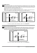
To prevent scratching the screen, set a cloth on a flat, level surface that will support the weight of the screen. Place 
screen face side down. If screen has knobs on the back, remove them to allow the adapter brackets to be attached. 
Place adapter brackets (

B

) on back of screen, align to holes, and center on back of screen as shown below. Attach 

the adapter brackets to the back of the screen using the appropriate combination of screws, multi-washers, and 
spacers as shown in figure 2.1, 2.2, or 2.3.

NOTE:

 Top and bottom holes must always be used.

Verify that all holes are properly aligned, and then tighten screws.

•  Tighten screws so adapter brackets are firmly attached. Do not tighten with excessive force. Overtightening can 

cause stress damage to screws, greatly reducing their holding power and possibly causing screw heads to become 
detached.


Tighten to 40 in. • lb (4.5 N.M.) maximum torque.

•  If screws don't get three complete turns in the screen inserts or if screws bottom out and bracket is still not tightly 

secured, damage may occur to screen or product may fail.

WARNING

CENTER BRACKETS 

VERTICALLY  

ON BACK OF 

SCREEN

NOTE:

 "X" dimensions should be equal.

B

NOTE: 

For 

flat back screens

 proceed to step 2-1. For 

bump-out or recessed back screen

 skip to step 2-2.

Notes:


•  The number of fasteners used will vary, 

depending upon the type of screen.

•  Multi-washers and spacers may not be 

used, depending upon the type of screen.

•  Use the corresponding hole in the multi-  

washer that matches your screw size.

MEDIUM HOLE FOR M5 SCREWS

SMALL HOLE FOR M4 SCREWS

LARGE HOLE FOR M6 SCREWS

MULTI-WASHER

2

Summary of Contents for LWS310/BK

Page 1: ... not provide sufficient space for proper ventilation on some screens Please refer to the manufacturer s requirements for mounting your screen before installation The screen must have a flat mounting surface or the mounting holes need to be on the furthest back surface of the screen Input Output connection must be properly oriented to accomodate mounting 0 4 from the wall Max Load Capacity 150 lb 68k...

Page 2: ...tached hardware and components Never exceed the Maximum Load Capacity See page one If mounting to wood wall studs make sure that mounting screws are anchored into the center of the studs Use of an edge to edge stud finder is highly recommended Always use an assistant or mechanical lifting equipment to safely lift and position equipment Tighten screws firmly but do not overtighten Overtightening can ...

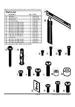
Page 3: ... X 12 mm phillips screws 6 504 9013 F M4 X 25 mm phillips screws 4 504 1015 G M5 X 12 mm phillips screws 4 520 1027 H M5 X 25 mm phillips screws 4 520 9543 I M6 X 12 mm phillips screws 4 520 1128 J M6 X 25 mm phillips screws 4 520 1208 K M8 X 16 mm phillips screws 6 520 9257 L M8 X 40 mm phillips screws 4 520 1136 M 219 ID x 5 OD spacers 4 540 1057 N 344 ID x 75 OD spacers 4 540 1059 O multi washe...

Page 4: ...all plate is level secure it using four 14 x 63 5 mm wood screws C as shown in fig 1 2 C A fig 1 2 fig 1 1 CENTER OF SCREEN A STUD 7 177 mm Installer must verify that the supporting surface will safely support the combined load of the equipment and all attached hardware and components Tighten wood screws so that wall plate is firmly attached but do not overtighten Overtightening can damage the screws ...

Page 5: ...ng out the back of the hole when entering a void or cavity Concrete must be 2000 psi density minimum Lighter density concrete may not hold concrete anchor Make sure that the wall will safely support four times the combined load of the equipment and all attached hardware and components WARNING Tighten screws so that wall plate is firmly attached but do not overtighten Overtightening can damage screw...

Page 6: ...y attached Do not tighten with excessive force Overtightening can cause stress damage to screws greatly reducing their holding power and possibly causing screw heads to become detached Tighten to 40 in lb 4 5 N M maximum torque If screws don t get three complete turns in the screen inserts or if screws bottom out and bracket is still not tightly secured damage may occur to screen or product may fa...

Page 7: ... space between the wall and the screen as shown in figure 2 2 Begin with longer length screw hand thread through washer adapter bracket and spacer in that order into screen as shown below Screw must make at least three full turns into the mounting hole and fit snug into place Do not over tighten If screw cannot make three full turns into the screen select a longer length screw from the baffled fasten...

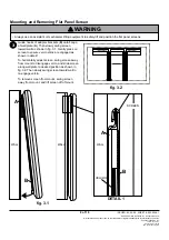
Page 8: ...hen slowly swing screen toward wall to re engage velcro To remove screen from mount swing screen away from mount and lift screen off of mount Mounting and Removing Flat Panel Screen 3 Always use an assistant or mechanical lifting equipment to safely lift and position the flat panel screens WARNING DETAIL 1 WALL VELCRO fig 3 1 WALL WALL SCREEN A B A B fig 3 2 2009 Peerless Industries Inc All rights re...

Page 9: ...ie ordnungsgemäße Lüftung Schlagen Sie bitte vor der Anbringung des Bildschirms die Montageanforderungen des Herstellers nach Der Bildschirm muss über eine flache Montagefläche verfügen oder die Montagebohrungen müssen sich an der Bildschirmfläche befinden die am weitesten nach hinten reicht E ingangs Ausgangsanschlüsse müssen so ausgerichtet sein dass die Montage 1 cm von der Wand entfernt möglich is...

Page 10: ...er Baukonstruktion verfügen und diese Anleitungen vollkommen verstehen Vergewissern Sie sich dass die tragende Fläche das Gesamtgewicht der Geräte und allen daran angebrachten Befestigungsteilen und Komponenten sicher tragen kann Die maximale Tragfähigkeit darf niemals überschritten werden Siehe Seite 9 Achten Sie bei der Anbringung an Holzständern darauf dass die Befestigungsschrauben jeweils in ...

Page 11: ...43 I M6 x 12 mm Schrauben 4 520 1128 J M6 x 25 mm Schrauben 4 520 1208 K M8 x 16 mm Schrauben 6 520 9257 L M8 x 40 mm Schrauben 4 520 1136 M Abstandhalter 5 6 mm ID x 12 7 mm AD 4 540 1057 N Abstandhalter 8 7 mm ID x 19 1 mm AD 4 540 1059 O Mehrlochscheiben 6 580 1036 P M6 x 20 mm Schrauben 4 520 9402 Q M6 x 30 mm Schrauben 4 510 9109 R M8 x 25 mm Schrauben 4 520 1031 Teileliste Die Teile können e...

Page 12: ...t ist und befestigen Sie sie wie in Abbildung 1 2 dargestellt mit Hilfe von vier Nr 14 x 63 5 mm Holzschrauben C C A A 7 177 mm 1 Installation zu verdoppeln Holzständerreihe Bei der Anbringung muss darauf geachtet werden dass die Wand die kombinierte Last von Bildschirm und allen Befestigungsteilen und komponenten tragen kann Ziehen Sie die Schrauben fest genug an dass die Wandplatte sicher befest...

Page 13: ...tondruckfestigkeit muss mindestens 2000 psi betragen In Beton mit geringerer Druckfestigkeit kann der Betondübel u U nicht halten Vergewissern Sie sich dass die Wand das Vierfache des Gesamtgewichts von Geräten und allen daran angebrachten Befestigungsteilen und Komponenten sicher tragen kann ACHTUNG Ziehen Sie die Schrauben fest genug an dass die Wandplatte sicher befestigt ist doch ohne sie zu ü...

Page 14: ... Sie die Schrauben nicht zu fest an Durch die beim Überdrehen entstehende Spannung können die Schrauben beschädigt werden was ihr Haltevermögen stark reduziert und möglicherweise dazu führen kann dass die Schraubenköpfe sich lösen Das maximale Drehmoment zum Festziehen der Schrauben darf 40 in lb 4 5 Nm nicht überschreiten Sind die Schrauben nicht um drei volle Umdrehungen in die Löcher des Bildsc...

Page 15: ...eginnen Sie mit der längeren Schraube und schrauben Sie diese in der unten abgebildeten Reihenfolge von Hand durch die Scheibe die Adapterhalterung und den Abstandhalter in den Bildschirm Die Schraube muss sich um mindestens drei volle Umdrehungen in die Montagebohrung drehen lassen und gut festsitzen Nicht zu stark anziehen Wählen Sie eine längere Schraube aus dem Befestigungsteilesortiment wenn ...

Page 16: ...vorsichtig auf den Bildschirm um sicherzustellen dass der Klettverschluss wie in Detailansicht 1 dargestellt geschlossen ist Zur horizontalen Einstellung des Bildschirms schwenken Sie diesen vom Halter weg um den Klettverschluss zu lösen und schieben ihn wie in Abbildung 3 2 dargestellt entlang der Wandplatte in die gewünschte Stellung Schwenken Sie den Bildschirm dann langsam in Richtung Wand um ...

Reviews: