background image

17

2016-01-12    #:180-9069-D

Cable Mangement and Soundbar Orientation

1.  Connect the soundbar’s male 3.5mm audio cable 

to the audio out port on the TV. Make sure the male 
3.5mm audio cable is fully inserted.

2.  Plug the soundbar’s power cable into the nearest 

outlet. 

3. Note

: If the audio output of the TV is RCA stereo, a 

female 3.5mm to male RCA stereo audio cable will 
be required.

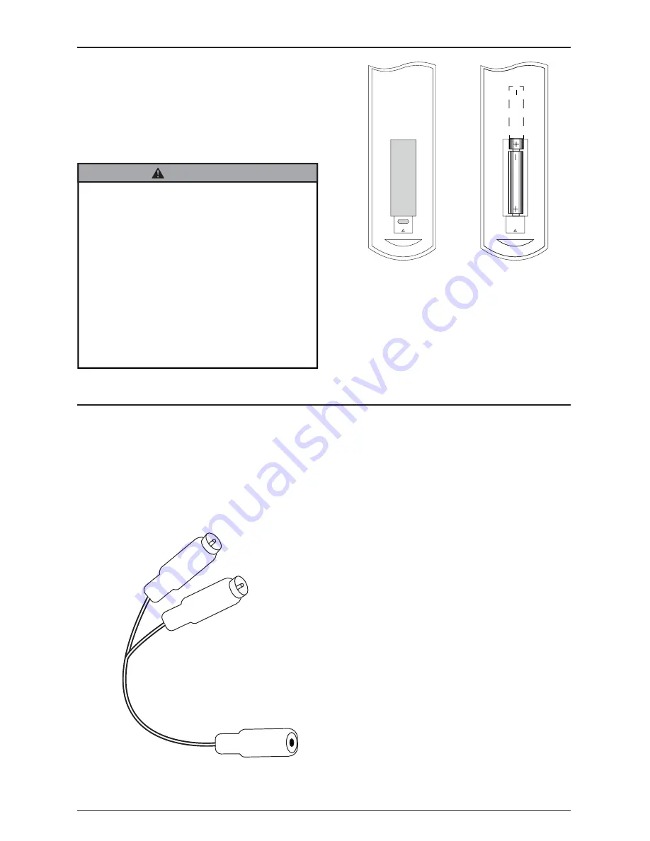
3.5mm female to male RCA stereo 
audio cable (sold seperately)

Battery Installation and Replacement

The remote control is powered by two 15V AAA batteries 
currently installed. 

To install or replace batteries:

1.  Replace the batteries by removing the battery cover 

and sliding in two new "AAA" batteries.

Important:

 Match the batteries to the (+) 

and (-) marks on the inside of the remote control.

2.  Snap the battery cover back onto the remote control.

Incorrect usage of batteries can result in leaks or 
bursting. Peerless-AV recommends the following 
battery use:
1.  Do not mix battery brands.

2.  Do not combine new and old batteries. This can 

shorten the battery life or cause liquid leakage of 
the batteries.

3.  Remove dead batteries immediately to prevent 

battery acid from leaking into the battery 
compartment.

4.  Do not touch exposed battery acid as it may 

injure skin.

5.  Remove the batteries if you do not intend to use 

the remote control for a long period of time.

 CAUTION

Summary of Contents for SPK-060

Page 1: ...1 2016 01 12 180 9069 D XTREMETM OUTDOOR SOUNDBAR MODEL SPK 060 User Manual www peerless av com...

Page 2: ...ty Always use an assistant or mechanical lifting equipment to safely lift and position equipment This product is intended for indoor use only Use of this product outdoors could lead to product failure...

Page 3: ...6 Installation Instructions 8 Mounting to a Wall 8 Mounting to a Display 14 Battery Installation and Replacement 16 Cable Managment and Soundbar Orientation 17 Operating Instructions 18 Using The Remo...

Page 4: ...it from the apparatus 7 Refer all servicing to qualified service personnel Servicing is required when the apparatus has been damaged in any way such as power supply cord or plug is damaged does not op...

Page 5: ...ct may be subject to any electromagnetic radiation causing failure 25 Do NOT leave any fire source such as candles close to or on the product as it may be a cause for fire or damages to the product 26...

Page 6: ...onnect the equipment into an outlet on a circuit different from that to which the receiver is connected 4 Consult the dealer or an experienced radio display technician for help This device complies wi...

Page 7: ...D left mount bracket 1 180 0268 E right mount bracket 1 180 0267 F remote control 1 remote G 14 x 2 5 wood screw 2 520 D1033 H 8mm concrete anchor 2 590 0320 I lock washer 2 540 3622 J nylon washer 2...

Page 8: ...8 2016 01 12 180 9069 D M 2 5 spacer N 2 25 spacer O 2 M5 x 10mm J 2 nylon washer K 2 M8 x 25mm 14 x 2 1 2 wood screw G 2 I 2 lock washer L 2 M8 x 40mm Q 1 4mm allen wrench 8mm concrete anchor H 2...

Page 9: ...9 D INSTALLATION INSTRUCTIONS Mounting to a Wall 1 1b 1 Wood stud wall Concrete Cinder block 1a 1 1a 1 Use stud finder to locate and mark stud center lines 1a 2 Level wallplate Mark mounting holes on...

Page 10: ...a 3 1a 4 Level wallplate Install using wood screws provided 5 32 4mm 3 8 10mm Drill mounting holes into supporting surface 2 5 64mm minimum depth required 2 Maximum 80 in lb 9 N M Mounting hole must c...

Page 11: ...016 01 12 180 9069 D 2 5 64mm 5 16 8mm 1b 1 1b 2 Level wallplate Mark mounting holes 5 16 8mm Do not drill into mortar joints Drill mounting holes into supporting surface 2 5 64mm minimum depth requir...

Page 12: ...12 2016 01 12 180 9069 D H 2 1b 4 Level wallplate Install using concrete anchors and wood screws provided 3 8 10mm 1b 3 Maximum 80 in lb 9 N M C G 4 Insert anchor flush to concrete H...

Page 13: ...13 2016 01 12 180 9069 D 3 2 Q B O x2 P 2 A Do not fully tighten...

Page 14: ...14 2016 01 12 180 9069 D 4 Q Hook brackets onto wall plate and tighten M5 screw A tighten B 2 SIDE VIEW 3 B 2 I 2 A K 2 O...

Page 15: ...15 7 23 6 400mm 600mm 7 9 15 7 200mm 400mm Position display screen side down on a flat clean surface Position soundbar grill side down either above or below display Determine which bracket configurat...

Page 16: ...6 01 12 180 9069 D Determine which hardware to use based on the depth needed Hardware included for installing soundbar only To attach display use hardware included with display mount 3 K K L L N J M M...

Page 17: ...eplace batteries 1 Replace the batteries by removing the battery cover and sliding in two new AAA batteries Important Match the batteries to the and marks on the inside of the remote control 2 Snap th...

Page 18: ...you don t hear any audio coming from the soundbar aim the remote at the soundbar and press the AUX button 3 To listen to a Bluetooth enabled device aim the included remote at the front of the soundbar...

Page 19: ...soundbar is plugged into an outlet that has power Ensure that the audio signal cable is connected to the audio out port on the TV Make sure that the source volume is not muted and that the volume leve...

Page 20: ...or removal of packing materials Damage due to improper incorrect or insufficient AC voltage Damage due to power surges or lightning strikes Damage which results from fire flood lightning tornado hurr...

Reviews: