Copyright © 2019 - PedalPCB.com
5
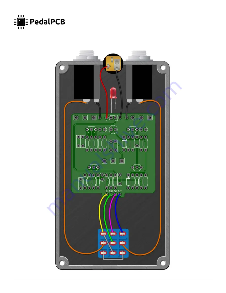
Mini Heterodyne Receiver
Wiring Diagram
Page 1: ...re Controls level of square wave fuzz Sub Controls level of subdivided frequency Super Controls level of multiplied frequency Sub Interval Rotary switch Sets the interval of subdivided voice Sub Root Toggle switch Selects the source of the subdivided root Super Interval Rotary switch Sets the interval of the multiplied voice Super Root Toggle switch Selects the source of the multiplied voice Porta...
Page 2: ...ne Receiver Important Assembly Instructions Apply a small piece of insulating tape Kapton tape electrical tape etc to the lugs of the Modulation Rate potentiometer to prevent contact with the metal housing of the Portamento Vibrato toggle switch ...
Page 3: ...BNSR IC7 CD4017BM IC8 CD4017BM DIODES D1 1N5817 POTENTIOMETERS OSC B100K RATE A500K SQUARE B100K SUB B100K SWITCHES OSC SW Mini 1P8T https www pedalpcb com product mini 1p8t SUB SW Mini 1P8T https www pedalpcb com product mini 1p8t SUB ROOT SPDT On On Short shaft toggle recommended GLIDE SPDT On On Short shaft toggle recommended OSC ROOT Type 2 DPDT On On On IMPORTANT NOTE OSC ROOT switch MUST be ...
Page 4: ...Copyright 2019 PedalPCB com 4 Mini Heterodyne Receiver ...
Page 5: ...Copyright 2019 PedalPCB com 5 Mini Heterodyne Receiver Wiring Diagram ...
Page 6: ...ure with top mounted jacks D C J A C K O U T P U T J A C K I N P U T J A C K F OOTSWITC H P O T ENTIO ME T E R LED P O T ENTIO ME T E R P O T ENTIO ME T E R P O T ENTIO ME T E R R O T ARY S WI T C H R O T ARY S WI T C H T O G GLE S WI T C H T O G GLE S WI T C H T O G GLE S WI T C H ...