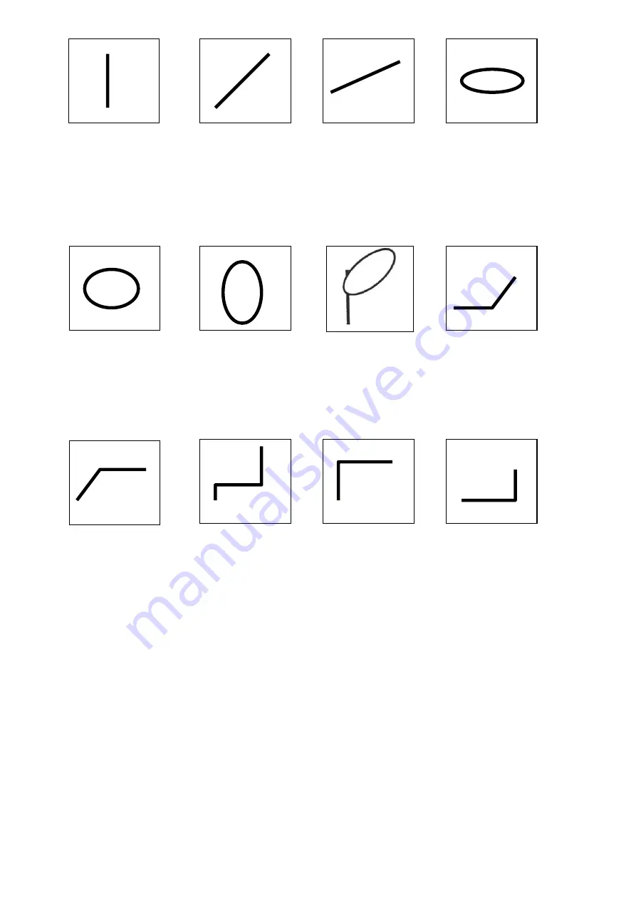
PeakTech 2020 GN Operation Manual Download Page 18

 
   a) Short circuit 

        b) Resistor 600 Ohm       c) Resistor 1,3 kOhm      d) A1. Capacitor 1µF 


    e) A1. Capacitor                 f) A1. Capacitor              g) Zener+Capacitor        h) Re Zener 
        4,7 µF                                  100 µF                              1 µF                                  (Forward) Diode 


   i) RZener                 j) Zener Diode                 k) Zener Diode              l) Silicon Diode 
      (Reverse)                              below 7 V                          beyond 7 V             


- 46 - 


Summary of Contents for 2020 GN

Page 1: ...ircuit before switching modes or functions do not cover the ventilation slots of the cabinet to ensure that the air is able to circulate freely inside do not insert metal objects into the equipment by way of the ventilation slots do not place water filled containers on the equipment danger of short circuit in case of knockover of the container do not operate the equipment near strong magnetic fiel...

Page 2: ...e humidity 45 85 2 After turning on power please allow a 20 minute pre heating period before use 3 Triple line power cord is to be used for the product But when you are using the doubleline cord make sure for safety 4 For quality improvement the exterior design and specifications of the product can be changed without prior notice 5 If you have further questions concerning use please contact your d...

Page 3: ...ification Input Coupling DC GND AC Rise Time 17 5 ns of less 35 ns or less x 5 MAG CH 1 Output Termination connection 25 mV div to 50 Ω 20 Hz to 10 MHz 3 dB Polarity Inversion CH 2 only Horizontal Deflection Display modes x 1 x10 VARIABLE X Y Time base 0 2 µs div to 0 2 s div in 19 calibrated steps with 1 2 5 sequence uncalibrated continuous control of over 2 5 times is possible Sweep Magnificatio...

Page 4: ... 7 8 kg Dimension 316 mm W x 132 mm H x 410 mm L Environmental Charac Temperature range 10 C to 35 C 50 F to 95 F for rated operation Max ambient operating temperature 0 C to 40 C 32 F to 104 F Max storage temperature 20 C to 70 C 4 F to 158 F Humidity range for rated operation 45 to 85 RH Max ambient operating humidity 35 to 85 RH Safety EN 61010 1 overvoltage CAT II degree of polution 2 Approval...

Page 5: ...ically don t leave this instrument in a close car exposed to sunlight in midsummer or next to a space heater Don t use this instrument immediately after bringing it in from the cold Allow time for it to warm to room temperature Similiary don t move it from a warm place to a very cold place as condensation might impair its operation Do not expose the instrument to wet or dusty environments Do not p...

Page 6: ...Fig 2 1 Front Panel Items Fig 2 2 Rear Panel Items 2 1 Function of controls connectors and indicators Before turning this instrument on familiarize yourself with the controls connectors indicators and other features described in this section The following descriptions are keyed to the items called out in Figures 2 1 and 2 2 34 ...

Page 7: ...nnel 2 or to the Y axis vertical amplifier during X Y operation Caution To avoid damage to the oscilloscope do not apply more than 400 V DC Peak AC between CH terminal and ground 25 CH1 AC GND DC switch To select the method of coupling the input signal to the CH 1 vertical amplifier AC position inserts a capacitor between the input connector and amplifier to block any DC component in the input sig...

Page 8: ...utput of the channel 1 signal suitable for driving a frequency counter or other instrument 2 1 3 Sweep and Trigger Blocks 15 TIME DIV switch To select either the calibrated sweep rate of the main timebase the delay time range for delayed sweep operation or X Y operation 13 CAL VAR switch to change between CALibrated Time Div steps and VARiable control 12 VARIABLE control Provides continuously vari...

Page 9: ...ggering occurs When rotated clockwise the trigger point moves toward the positive peak of the trigger signal When its control is rotated counter clockwise the trigger point moves toward the negative peak of the trigger signal 8 Trigger SLOPE switch To select the positive or negative slope of the trigger signal for initiating sweep 19 EXT TRIG IN connector For applying external trigger signal to th...

Page 10: ... Adjust brightness to your liking Caution A burn resistant material is used in the CRT However if the CRT is left with an extremely bright dot or trace for a very long time the screen may be damaged Therefore if a measurement requires high bright ness be certain to turn down the INTEN control immediately afterward Also get in the habit of turning the brightness way down if the scope is left unatte...

Page 11: ...l sources and equipment having output connectors The outer conductor of the cable shields the central signal conductor from hum and noise pickup These cables are usually fitted with BNC connectors of each end and specialized cable and adaptors are readily available for mating with other kinds of connectors Scope probes are the most popular method of connecting the oscilloscope to circuitry These p...

Page 12: ...rectly to the AC power line or any circuitry connected directly to the power line Damage to the instrument and severe injurt to the operator may result from failure to heed this warning 2 2 3 Single trace Operation Single trace operation with single timebase and internal triggering is the most elementary operating mode of the PeakTech 2020 GN or PeakTech 2030 KT Use this mode when you wish to obse...

Page 13: ...not riding on a high amplitude DC voltage You will also have to reset the Trigger MODE switch 14 to NORM if the signal frequency is below 25 Hz and possibly readjust the Trigger LEVEL control 9 2 2 4 Dual trace operation Dual trace operation is the major operating mode of the PeakTech 2020 GN and PeakTech 2030 KT The setup for dual trace operation is identical to that of 2 3 2 Single trace operati...

Page 14: ...ignal and a vertically deflected but non synchronized display when vertical signal is present but the trigger controls are improperly set This immediately indicates what is wrong The only hitch with AUTO operation is that signals below 25 Hz cannot and complex signals of any frequency may not realiably trigger the timebase Therefore the usual practice is to leave the trigger MODE switch 14 set to ...

Page 15: ...n doubt or have an unsatisfactory display try both slopes to find the best way Trigger Level Control The LEVEL control determines the point on the selected slope at which the main A timebase will be triggered The effect of the LEVEL control on the displayed trace is shown in figure 2 4 c The 0 and panel markings for this control refer to the waveform s zero crossing and points more positive and mo...

Page 16: ...aph 2 3 4 Dual trace Operation 2 Make sure both VOLTS DIV switches 26 and 23 are set to the same position and the VARIABLE controls 27 and 20 are click stopped fully clockwise Are the signal levels are very different set both VOLTS DIV switches to the position producing a large on screen display of the highest amplitude signal 3 Trigger from the channel having the best signal 4 Set the V MODE swit...

Page 17: ...27 knob set CAL 4 Adjust the trace position vertically Y axis with the CH2 Vertical POSITION control 7 Adjust the trace position horizontally X axis with the Horizontal POSITION control 10 the CH 1 Vertical POSITION control has no effect during X Y operation 5 Vertical Y axis sign may change the phase by 180 setting CH 2 INV switch 2 2 9 Component Test Operation Only PeakTech 2030 KT The component...

Page 18: ...Ohm c Resistor 1 3 kOhm d A1 Capacitor 1µF e A1 Capacitor f A1 Capacitor g Zener Capacitor h Resistor Zener 4 7 µF 100 µF 1 µF Forward Diode i Resistor Zener j Zener Diode k Zener Diode l Silicon Diode Reverse below 7 V beyond 7 V 46 ...

Page 19: ...ages To measure peak to peak voltage proceed as follows 1 Set up the scope for the vertical mode desired per the instructions in 2 3 BASIC OPERATING PROCEDURES 2 Adjust the TIME DIV switch 15 for two or three cycles of waveform and set the VOLTS DIV switch for the largest possible totally on screen display 3 Use the appropriate Vertical POSITION control 4 or 7 to position the negative signal peaks...

Page 20: ...tion any point of interest on the central vertical gratitude line This line has additional calibration marks equal to 0 2 major division each The voltage relative to ground at any point selected is equal to the number of divisions from that point to the ground reference line multiplied by the VOLTS DIV setting In the example used for figure 2 6 the voltage for a 0 5 V div scale is 2 5 V 5 0 div x ...

Page 21: ...is conveniently 1 5 divisions so the pulse width is 15 milliseconds However 1 5 division is a rather small distance for accurate measurements so it is advisable to use a faster sweep speed for this particular measurement Increasing the sweep speed to 2 ms div as in Figure 2 7 gives a large display allowing more accurate measurement If it is seen small with the TIME DIV switch you may measure X 10 ...

Page 22: ...nel with the cleanest and most stable trace Temporarily move the other channel s trace off the screen by means of it Vertical POSITION control 3 Center the stable trigger source trace with its Vertical POSITION control and adjust its amplitude to exactly 6 vertical divisions by means of its VOLTS DIV switch and VARIABLE control 4 Use the Trigger LEVEL control 9 to ensure that the trace crosses the...

Page 23: ...us pattern method proceed as follows 1 Rotate the TIME DIV switch fully clockwise to its X Y position Caution Reduce the trace intensity least the undeflected spot damage the CRT phosphor 2 To measure by setting INV to NORM and X5 MAG to X1 3 Connect one signal to the CH 1 or X IN connector 24 and the other sight to the CH 2 or Y IN connector 22 4 Center the trace vertically with the CH2 Vertical ...

Page 24: ...isetime Measurement Risetime is the time for the leading edge of a pulse to rise from 10 to 90 of the total pulse amplitude Falltime is the time required for the trailing edge of a pulse to drop form 90 of total pulse amplitude to 10 Risetime and falltime which may be collectively called transition time are measured in essentially the same manner To measure rise and fall time proceed as follows 1 ...

Page 25: ...eps 7 and 8 10 When measuring the rise and fall time note that 17 5 ns Rise time tr 0 35 f 3dB which is transition time is contained in the PeakTech 2020 GN oneself Therefore the real transition time tc is composed of measure transistion time tm and tr The above all is explained with the following formula tc tm tr tc Real transition time tm Measured transition time tr Rise time of oscilloscope a B...

Page 26: ...3 2 Calibration interval To maintain the accuracy specifications of the PeakTech 2020 GN PeakTech 2030 KT calibration checks and procedures should be performed after every 1000 hours of service However if the instrument is used infrequently the calibration checks should be performed every six months Fig 3 1 Front Case and Filter All rights also for translation reprinting and copy of this manual or...

Page 27: ...sic operation procedures 38 2 2 1 Preliminary control settings and adjustments 38 2 2 2 Signal Connections 39 2 2 3 Single trace operation 40 2 2 4 Dual trace operation 41 2 2 5 Trigger Options 42 2 2 6 Measurement of different frequency 44 2 2 7 Additive and Differential operation 44 2 2 8 X Y operation 45 2 2 9 Component test operation only PeakTech 2030 KT 45 2 3 Measurement applications 47 2 3...

Page 28: ...20 MHz Analog Oszilloskop 20 MHz analogue oscilloscope PeakTech 2020 GN PeakTech 2030 KT Bedienungsanleitung Operation Manual PeakTech Spitzentechnologie die überzeugt ...

Reviews: