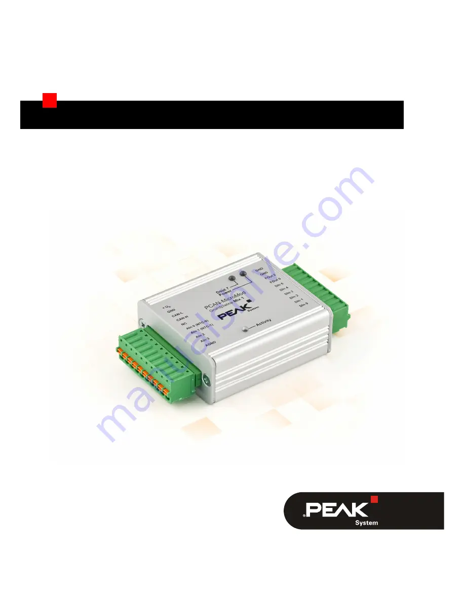
PCAN-MicroMod Mix 1
Application-specific PCAN-MicroMod Motherboard
User Manual
Document version 1.11.2 (2017-02-03)
Page 1: ...PCAN MicroMod Mix 1 Application specific PCAN MicroMod Motherboard User Manual Document version 1 11 2 2017 02 03...
Page 2: ...community trade marks of CAN in Automation e V All other product names mentioned in this document may be the trademarks or registered trademarks of their respective companies They are not explicitly...
Page 3: ...wn Circuits for the Digital Inputs 9 2 3 Measuring Range Extension of the Analog Inputs 11 3 Operation 12 3 1 Port Assignment 12 3 2 Configuration Program 13 3 2 1 System Prerequisites 13 3 2 2 Instal...
Page 4: ...and supports temperature measurement Note This manual only refers to the motherboard as base for a PCAN MicroMod and to the standard firmware For the PCAN MicroMod and the configuration program PCAN...
Page 5: ...fast status changes countings 2 temperature inputs for connection of thermistors type EC95F103W measuring range 0 to 70 C 32 to 158 F 2 analog inputs Pull down circuit Measuring range unipolar 0 to 5...
Page 6: ...26 V DC For creating and transferring configurations computer with Windows 10 8 1 7 32 bit or 64 bit and a CAN interface from the PCAN series 1 3 Scope of Supply PCAN MicroMod PCAN MicroMod motherboar...
Page 7: ...following sections unscrew the lid of the casing and pull off the MicroMod from the motherboard Attention Electrostatic discharge ESD can damage or destroy components on the motherboard or the PCAN Mi...
Page 8: ...x 1 motherboard with a nominal voltage Ub 12 V usually 24 V then you must do the following modification 1 Equip the unpopulated position D6 with a reference diode BZV55C12 package SOD 80 Figure 2 Posi...
Page 9: ...automotive sector up to 18 V may occur at a nominal voltage of 12 V 2 2 Pull up Pull down Circuits for the Digital Inputs At delivery the digital inputs are set to pull up circuits You can set them to...
Page 10: ...10 Figure 4 Positions R31 R53 R55 R54 R56 top side of the PCB Figure 5 Position R12 bottom side of the PCB Attention Double check for inadvertent short circuits after altering the setup especially at...
Page 11: ...On delivery of the motherboard the resistor positions R30 and R43 on the bottom side of the PCB are not equipped By inserting a resistor Rx package S0805 with a value calculated with the following for...
Page 12: ...ment is as follows Figure 7 Ports of the Mix 1 motherboard Port name J1 2 Function Ub Operating voltage 8 26 V DC See also section 2 1 Modification on Nominal Supply Voltages 12 V on page 8 GND Digita...
Page 13: ...the Win dows software PCAN MicroMod Configuration is used This section covers basic points about installation and use of the program with the Mix 1 motherboard You ll find detailed information about t...
Page 14: ...n PCAN MicroMod Configuration the Board Type dialog box appears in order to select the type of the used motherboard The necessary settings are explained in the following Figure 8 PCAN MicroMod Configu...
Page 15: ...rolled by the servi ces of the MicroMod The following table shows the assignment of the motherboard functions to the MicroMod services Function on motherboard Port name Access with MicroMod service s...
Page 16: ...the CAN Bus If you want to use several MicroMods on the same CAN bus and want to configure them each one needs its own module number That way the MicroMods are distinguishable for the program PCAN Mic...
Page 17: ...the motherboard or the PCAN MicroMod Take precautions to avoid ESD when handling the boards Remounting the MicroMod When you remount the MicroMod take notice of the white triangu lar marks on each th...
Page 18: ...ctronic components Digital inputs Count 6 Switching thresholds UIH 4 V UIL 3 V contact or logic level Input impedance 2 7 k Open input Pull up optionally pull down in groups Overvoltage protection ext...
Page 19: ...AN Transmission standard High speed CAN ISO 11898 2 typ 500 kbit s setup with PCAN MicroMod Configuration Windows software Termination none CAN ID reserved for configuration transfer 0x7E7 Module numb...
Page 20: ...erature for storage and transport 40 100 C 40 212 F Relative humidity 15 90 not condensing Ingress protection IEC 60529 IP20 EMC Directive 2014 30 EU DIN EN 61326 1 2013 07 Measures Casing size incl c...
Page 21: ...PCAN MicroMod Mix 1 User Manual 21 Appendix A CE Certificate...
Page 22: ...PCAN MicroMod Mix 1 User Manual 22 Appendix B Dimension Drawing Figure 10 Top view and view of front side with connector The figure does not show the actual size of the product...