


Installation and Operating Handbook
Section 1
Unit Description
The PBU2000 incorporates two fixed block up conversion stages along with microprocessor control and moni
toring of internal functions. Switching between the bands is accomplished via. one of the interfaces. If option
11 is supplied, then both band outputs are available simultaneously.
Remote control is available from the front panel connections, RS232/RS485 and ethernet, as well as via
the local wired interface. The internal oscillator is fed from an internal reference, which can also be locked to an
externally provided 10MHz reference frequency to ensure the system is stable and the changeover from one
PBU2000 converter to another, minimises traffic interruption.
1.1
Specification
Please refer to the PBU2000 datasheet for the current standard performance, or contact technical support for
specific technical enquiries.
1.2
Chassis
The unit is housed in a sealed die cast aluminium box. See Appendix A for the dimensions details.
1.3
Mounting
The unit comes with two mounting options:
Flat surface
Two small brackets are supplied for fixing of the unit to a flat surface. The brackets need to be screwed
to the unit’s underside in the appropriate place.
Pole
A kit to mount the unit to a circular pole is supplied.
See Appendix A for details.
1.4
Connections
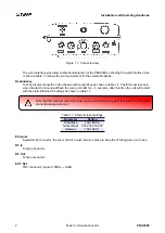
Figure 1.1 shows a connector view.
Breather
Immersion proof breather.
Fuse
The main DC power supply fuse, bulkhead mounting 20mm x 5mm 2 Amp removable by turning.
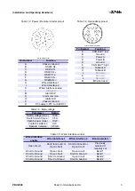
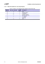
Power / Remote / Alarms
16 Way male circular on the chassis with connections as shown in table 1.2. The cable must be rated to
cope with 2 Amp continuous use. The alarm contacts are from a dry contact relay, the ratings of which
are shown in table 1.3
PBU2000
Peak Communications Ltd.
1
Summary of Contents for PBU2000
Page 2: ......