background image

PCAN-PCI Express FD – User Manual 
 

36 

5


Technical Specifications 

Connectors 


Computer 

PCI Express x1 (1 lane); 
electromechanical specification 2.x 

CAN 

D-Sub (m), 9 pins 
Pin assignment according to specification CiA® 303-1 


CAN 


Protocols 

CAN FD ISO 11898-1:2015, CAN FD non-ISO, CAN 2.0 A/B 

Physical transmission 

ISO 11898-2 (High-speed CAN) 

CAN bit rates 

25 kbit/s - 1 Mbit/s 

CAN FD bit rates 

25 kbit/s – 12 Mbit/s 

Controller FPGA 

implementation 

Transceiver NXP 

TJA1044GT 

Galvanic isolation 

up to 500 V, separate for each CAN channel 

Supplying external 

devices 

D-Sub pin 1; 5 V, max. 50 mA 
disabled at delivery 

Daisy chain 

(only IPEH-004040) 

via solder bridges, disabled at delivery 

Internal termination 

via solder bridges, disabled at delivery 


Power supply 

Current consumption 

Product version 

Single Channel 
Dual Channel 
Four Channel 

at 3.3 V pin 

max. 200 mA 
max. 200 mA 
max. 200 mA 

at 12 V pin 

max. 50 mA 
max. 70 mA 
max. 100 mA 


Environment 

Operating temperature 

-40 - +85 °C 

Temperature for storage 

and transport 

-40 - +125 °C 

Relative humidity 

15 - 90 %, not condensing 

EMC Directive 

2014/30/EU 

DIN EN 55024:2016-05 
DIN EN 55022:2011-12 


Continued on the next page 

Summary of Contents for IEPH-004040

Page 1: ...PCAN PCI Express FD CAN FD Interface for PCI Express User Manual Document version 1 2 0 2017 06 15...

Page 2: ...n this manual may be the trademarks or registered trademarks of their respective companies They are not explicitly marked by and Copyright 2017 PEAK System Technik GmbH Duplication copying printing or...

Page 3: ...g the Daisy Chain 14 3 5 Activating the Internal Termination 18 3 6 Cabling 20 3 6 1 Termination 20 3 6 2 Example of a Connection 20 3 6 3 Maximum Bus Length 21 4 Software and API 22 4 1 Monitor Softw...

Page 4: ...PCAN PCI Express FD User Manual 4 5 Technical Specifications 36 Appendix A CE Certificate 38 Appendix B Dimension Drawing 39 Appendix C Quick Reference 40...

Page 5: ...o the CAN 2 0 A B standard thus CAN FD nodes can be used in existing CAN networks However in this case the CAN FD extensions are not applicable The monitor software PCAN View and the programming inter...

Page 6: ...rately for each CAN channel PCI Express data transfer via bus master DMA DMA memory access operations with 32 and 64 bit addresses Measurement of bus load including error frames and overload frames on...

Page 7: ...ly Plug in card PCAN PCI Express FD Slot bracket with D Sub connectors for the CAN bus only four channel version Device drivers for Windows 10 8 1 7 and Linux 32 64 bit CAN monitor PCAN View for Windo...

Page 8: ...vers and click on Install now 3 Confirm the message of the User Account Control related to Installer database of PEAK Drivers The driver setup starts 4 Follow the program instructions Do the following...

Page 9: ...d completes the driver installation Do the following to check the operational readiness 1 Open the Windows Start menu 2 Type peakcpl and press Enter The information window for PEAK hardware appears Th...

Page 10: ...he 9 pin D Sub connector The pin assignment for CAN corresponds to the specification CiA 303 1 Figure 1 Position of the sockets on the four channel card IPEH 004040 dual channel card IPEH 004027 only...

Page 11: ...dard via a bus converter PEAK System offers different bus converter modules like the PCAN TJA1054 for a Low speed CAN bus according to ISO 11898 3 3 2 Slot Bracket with D Sub Connectors Figure 3 Dual...

Page 12: ...nwanted short circuits on the card Attention Electrostatic discharge ESD can damage or destroy components on the card Take precautions to avoid ESD Set the solder bridges corresponding to the desired...

Page 13: ...the bottom side of the four channel card IPEH 004040 for a 5 Volt supply dual channel card IPEH 004027 only CAN 1 and CAN 2 single channel card IPEH 004026 only CAN 1 5 Volt supply D Sub connector Sol...

Page 14: ...xisting CAN bus This makes interference free operation possible at higher CAN FD bit rates because stubs and Y distributions are largely avoided When the daisy chain is activated the pin assignment ch...

Page 15: ...destroy components on the card Take precautions to avoid ESD Set the solder bridges corresponding to the desired settings Figure 6 on page 16 shows the solder field positions on the top of the four c...

Page 16: ...the top side of the card IPEH 004040 for the activation of the daisy chain Daisy chain D Sub connector Solder field Without standard Active CAN1 JP18 CAN2 JP20 Attention For CAN 1 and CAN 2 additiona...

Page 17: ...he card IPEH 004040 for the activation of the daisy chain Daisy chain D Sub connector Solder fields Without standard Active CAN1 JP17 CAN2 JP19 CAN3 JP13 and JP14 CAN4 JP15 and JP16 Attention For CAN...

Page 18: ...termination Risk of short circuit Solder with great care to avoid unwanted short circuits on the card Attention Electrostatic discharge ESD can damage or destroy components on the card Take precaution...

Page 19: ...four channel card IPEH 004040 for the internal termination dual channel card IPEH 004027 only CAN 1 and CAN 2 single channel card IPEH 004026 only CAN 1 Internal termination D Sub connector Solder fi...

Page 20: ...oper operation of the transceivers of the connected CAN nodes CAN interfaces control devices The PCAN PCI Express FD card has an optional internal termination with 120 ohms For more information see ch...

Page 21: ...t rate Bus length 1 Mbit s 40 m 500 kbit s 110 m 250 kbit s 240 m 125 kbit s 500 m 50 kbit s 1 3 km 25 kbit s 2 5 km The listed values have been calculated on the basis of an idealized system and can...

Page 22: ...ded software PCAN View and the programming interface PCAN Basic 4 1 Monitor Software PCAN View PCAN View is a simple Windows software to view transmit and log CAN and CAN FD messages Note This chapter...

Page 23: ...ck Frequency The selectable bit rates in the following are based on this setting 4 From the drop down list select a Nominal Bit rate which is used for the arbitration phase max 1Mbit s 5 Enable the Da...

Page 24: ...standard frames 11 bit IDs or for extended frames 29 bit IDs 8 Activate the Listen only mode if you do not actively participate in the CAN traffic and just want to observe This also avoids an unintend...

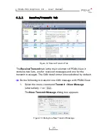
Page 25: ...View It contains two lists one for received messages and one for the transmit messages The CAN data format is hexadecimal by default Do the following to transmit one CAN message with PCAN View 1 Selec...

Page 26: ...transmission Enter a value greater than 0 to transmit periodically Enter the value 0 to transmit only manually 5 Enable the Bit Rate Switch checkbox that the data of a CAN FD message is transmitted wi...

Page 27: ...unication on a CAN bus During this process the messages are cached in the working memory of the PC Afterwards they can be saved to a file The Tracer runs either in linear or in ring buffer mode The li...

Page 28: ...ut the hardware and driver CAN FD ISO mode The defined in the ISO 11898 standard is not compatible with the original protocol PEAK System takes this into account by supporting both protocol versions w...

Page 29: ...al 29 4 1 4 Bus load Tab Figure 16 Bus load tab On the Bus Load tab the current bus load time course and statistical information of the CAN channel are displayed The CAN bus load reflects the utilizat...

Page 30: ...must be recognized as an error by the connected CAN nodes You can destroy CAN frames with the error generator by one of two methods once after activation repeatedly at specific intervals related to a...

Page 31: ...of Frames to ignore field specifies the number of CAN frames with the given ID that are ignored before a frame is destroyed 4 The Number of Frames to destroy field specifies the number of CAN frames w...

Page 32: ...rovided DVD you can find files of the PCAN Basic programming interface in the directory branch Develop This API provides basic functions for linking own programs to CAN and CAN FD interfaces by PEAK S...

Page 33: ...the operating systems Windows 10 8 1 7 32 64 bit Windows CE 6 x and Linux 32 64 bit Multiple PEAK System applications and your own can be operated on a physical channel at the same time Use of a singl...

Page 34: ...iption of the API The PCAN Basic API is the interface between the user application and device driver In Windows operating systems this is a DLL Dynamic Link Library The sequence of accessing the CAN i...

Page 35: ...ommunication the function CAN_Uninitialize is called in order to release the reserved resources for the CAN channel among others In addition the CAN channel is marked as Free and is available to other...

Page 36: ...c isolation up to 500 V separate for each CAN channel Supplying external devices D Sub pin 1 5 V max 50 mA disabled at delivery Daisy chain only IPEH 004040 via solder bridges disabled at delivery Int...

Page 37: ...PCAN PCI Express FD User Manual 37 Measures Size PCB 121 x 114 mm H x W See also dimension drawing in Appendix B on page 39 Weight Single Channel Dual Channel Four Channel 55 g 66 g 73 g...

Page 38: ...PCAN PCI Express FD User Manual 38 Appendix A CE Certificate...

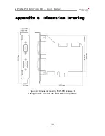
Page 39: ...PCAN PCI Express FD User Manual 39 Appendix B Dimension Drawing Figure 20 Dimension drawing PCAN PCI Express FD The figure does not show the actual size of the product...

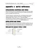
Page 40: ...Windows start and the driver is initialized Check the operational readiness Open the Windows Start menu Type peakcpl and press Enter An information window for PEAK Hardware opens The plug in card mus...

Reviews: