


Installation and Operating Handbook
3.2.5.3
Instruction 6, Sub Instruction ’2’ (TCP Port Change Request)
This message is sent to the unit, when the host computer wishes to change the TCP Port settings of the
TLTR3100 unit. The unit does not need to be in remote mode for this to be achieved.
Table 3.18: TCP Port Change Request message format (instruction 6, sub instruction ’2’)
Message
byte no.
Set value / example
Length
(bytes)
Description
1
02
1
STX
2
18
1
Number of bytes
3
32
1
Unit address
4
6
1
Instruction number
5
'2'
1
Sub instruction
6
'04000'
5
TCP port number
11
'.'
1
Separator character
12
'00010'
5
TCP socket timeout in seconds
17
?
1
Checksum
18
03
1
ETX
3.3
Ethernet
If the TLTR3100 unit has been fitted with the Ethernet option the unit can be controlled via its in built web server,
TCP or SNMP.
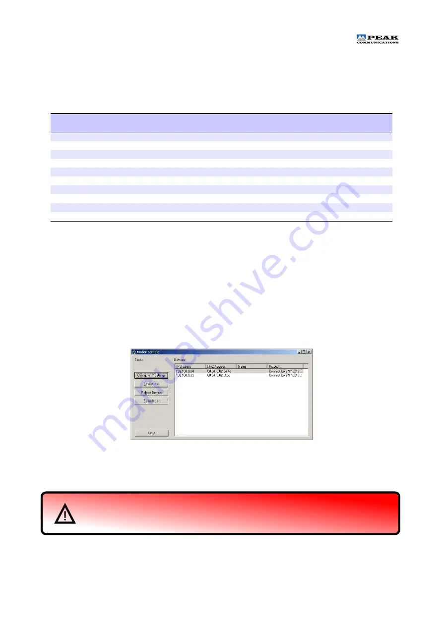
Due to a lack of front panel on these units, it is not possible to display the IP address and other Ethernet
settings to the user easily. In order to discover the IP address and other Ethernet settings, initially only, the
ethernet discovery windows programme needs to be run. This software is available from the Peak Communi
cations website. When run it lists the units on the network, and allows the user to view and modify, if necessary,
the Ethernet settings to suit the user’s network, see figure 3.1.
Figure 3.1: Ethernet discovery
The ’Configure IP Settings’ button brings up the window as shown in figure 3.2. This allows the changing
of the Ethernet settings, the password is ”PEAKpass123”, it is case sensitive.
The TLTR3100 units do leave the factory in DHCP mode, as such they need to be setup via a
DHCP network. If this isn’t available then it is possible to force the unit onto a static IP address,
see the Ethernet Reset pin’s details on page 2.
TLTR3100
Peak Communications Ltd.
23


