background image


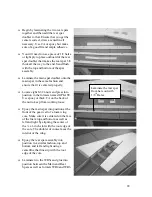
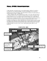
Continue one strip at a time until you get to the location of the nose gear. 


You will need to have the gear in place at this time. 


Raise the gear leg out of the fuselage and note where it contacts the wood and begin 
to cut away the necessary balsa to make the opening.  


Continue to add a piece of balsa and make the opening one at a time until you have 
completely covered the bottom of the fuselage. 


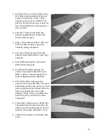
Use the ¼ x 1/8 x 36 Spruce to make reinforcement on the bottom sheeting from the 
inside, both behind BH3 and in front of BH2 next to the gear opening for added 
strength.  


Sand the edges of the sheeting flush with the fuselage sides. 


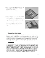
Add the balsa nose block to the fuselage and sand the entire front of the fuselage to 
shape.  


Go over the entire model and fill any voids and sand to satisfaction.   


Stabilizers and Vertical Fins 

 
The Stabilizers and Vertical Fins are constructed and finished in an almost identical 
manner as the main wing. Since you now see the process we will just stick to the details 
and you can use similar methods and materials as before. 


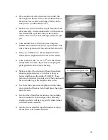
Use the supplied sheets of 1/16

th

 x 4 x 36 balsa to make up the individual skins for the 

stabilizers and Vertical Fins. Just as with the wing use the cradle to lay out your skins 
and keep in mind that you will need about ½ inch extra at the rear. Also the sheeting 
is parallel at the front and rear of the core, just as before. 


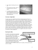
Apply the skins and square up all edges. 


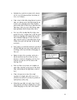
Trial fit each individual surface into position on a respective spar. You will notice 
that there needs to be an angle sanded into the root for a good fit, do so now.  

 
Just as with the wings, you will cut away ½ inch of material within the individual flight 
surfaces, then build back with ¼ front and rear. 


36

Summary of Contents for DV8R

Page 1: ......

Page 2: ...ks and performance usually found in far more expensive jets but in a package that fits a wide range of modeler s skills With its large size light wing loading and generous landing gear stance the DV8R has an incredible flight envelope that will prove favorable to nearly any jet pilot We are so impressed with DV8R s flight prowess it s smoothness and it s extreme stability at all speeds that we thi...

Page 3: ...ms you will need to obtain to finish your model Options such as landing gear brakes fuel tanks servo mounts and more can be purchased directly from PCM In many of the instructions and photos that follow some of these items are mentioned or referred to during the construction process Please feel free to contact us for more information concerning these items What Is Needed To Start As we mentioned e...

Page 4: ...ngine and its associated hardware as well as the onboard radio gear etc We will make suggestions based upon our experience with the DV8R as well as the experience gained with other models The final selection installation and operation of this equipment is left entirely up to you and your experience Engine selection Please READ The factory DV8R is flying with a JetCat P80 which is a perfect match f...

Page 5: ...lywood 15 BH2A X 1 1 8th Plywood 16 BH3 X 1 1 8th Plywood 17 BH3A X 1 1 8th Plywood 18 BH4 X 1 1 8th Plywood 20 BH6 X 1 1 8th Plywood 20 BH7 X 1 1 8th Plywood 21 BH8 X 2 1 8th Plywood 22 HF1 X 2 1 8th Plywood 23 HF2 X 2 1 8th Plywood 24 HF3 X 6 1 8th Plywood 25 HF4 X 1 1 8th Plywood 26 x 3 8 x 4 Maple Motor Mount x 2 27 x x 36 Balsa Triangle Stock x 10 28 1 8 x 1 x 8 1 2 Ply Strip x 1 29 x x 36 Sp...

Page 6: ...Plywood 12 GPLATE X 2 1 4 Plywood 13 WR1A X 2 1 4 Balsa 14 GP1 X 2 1 4 Balsa 15 GP2 X 2 1 4 Balsa 16 Balsa Wing Tips x 2 17 3 8 x 3 x 48 Balsa Sheet x 1 18 x 3 x 36 Balsa Sheet x 2 19 1 8 x 4 x 48 Balsa Sheet x 16 20 1 8 x 4 x 36 Balsa Sheet x 4 21 x 1 1 2 Birch Dowels x 2 22 20 x 2 Aluminum Wing Bolts with Washers x 2 23 Flat Nylon Hinges x 18 24 x 3 4 x 1 1 4 Ply Hinge Plates 25 Chrome Steel Con...

Page 7: ...tabilizer Tips x 2 7 Balsa Fin Tips x 2 8 1 16th x 4 x 36 Balsa Sheet x 10 9 x 2 x 36 Balsa Sheet x 3 10 x 1 Birch Dowels x 4 11 Nylon Flat Hinges x 16 12 Carbon Control Horns x 2 13 Chrome Steel Control Horn With Bushing x 2 14 2 56 x Button Head Screws x 4 15 x x 1 1 4 Ply Hinge Plates 16 4 40 Steel Control Rods x 4 17 4 40 Solder Clevises x 4 18 4 40 Steel Clevises x 4 6 ...

Page 8: ...conclude with the following VERY IMPORTANT BE SURE OF THE ORIENTATION OF ALL PARTS BEFORE FINAL GLUING We begin by constructing one tail boom section in the photos you will see both booms being constructed so you may begin with either side but it would be best to finish one then go back and build the other Locate the two motor mounts MM and two x 3 8 x 4 Hardwood Blocks and epoxy or CA them secure...

Page 9: ...e motor ount as shown on a e squareness of the boom Once satisfied with the fit add the former FF6 and once again ensure th the fit is at Now you can use a sanding block square up the edges of the balsa triangle at the fro sh Locate the motor mount assembly corresponds to the boom you are building The hardwood piece is located away from the center m Using balsa triangle add pieces to the rear and ...

Page 10: ...lowing photos Repeat all of the above steps build the other boom Don t forget that you must b J You will need to place the two halv on an elevated surface to allow the Stabilizer spars to hang off the side This will allow t Locate former BH7 and fit to the structure as shown At the bottom you will add a piece of balsa triangle and then install the 1 8 x 1 x 8 and 5 8 strip join b Place the assembl...

Page 11: ...curely glued and that the boom structure is straight and square Some of the interior areas around the motor mount will be visible on the completed model If you wish to paint or finish this area now would be a good time This concludes this portion of the assembly at this time 10 ...

Page 12: ... laminate formers BH3 and BH3A aligning the holes Glue BH2A into position on BH2 as shown the top and glue into position rmers As shown in the photo ther side of the int shown here Press four 6 32 t nuts into the holes in BH2A from Locate former BH6 and trial fit into the slots in the center of the BH3 assembly IMPORTANT Make sure the doubler BH3A is on the opposite side of the joint between the t...

Page 13: ...s together first and use glue only when you are sure everything is correct When p x en roperly built ere are no gaps between these form rive to get a good fit at all joints to e joints Fuselage sides to the rear of BH6 ing the fuselage sides into position e should be square and straight H1 extreme front of the model th ers and this is what you should strive for IMPORTANT No glue in this area Place...

Page 14: ... at this time and securely glue most of the joints it is VERY IMPORTANT that the fuselage sides only be tack glued to the former BH6 towards the rear of this assembly In a later step when the rear section booms are fitted to the front section you will need to spread the sides apart just slightly to bring the fuselag sections together You may use clamps at this time to tempora From the 1 x 1 x 36 b...

Page 15: ...up Locate the materials to make up the contr NOTE When setting up your steering first screw the four 2 56 eyelet screws into the 2 56 clevises about a 1 16th of an inch only Connect the clevises to the servo arm and steering arm at the top the strut Holding the strut and servo straight use the supplied steering cab a TIP Remember that these lines will stretch a little when first used and you will ...

Page 16: ...d everything tightly in place while checking for squareness and fit The keys to the fit of the two sections are the tabs on the former BH7 and the corresponding slots and tabs on the fuselage sides and BH6 Carefully align the two sections and ensure that the fit of all joints are tight and proper Use a medium CA to begin tacking all joints working a little at a time until you have a good fit 15 ...

Page 17: ...s of ply as shown at right The front of former FF7 will but up against the back of formers HF1 hatch formers Glue one of the balsa FF8 pieces into place in the opening between the fuselage sides and the top of the fuselage as shown Repeat for both sides and then laminate a second FF 8 into position on top of the first completely filling the void From the inside of the fuselage you can go back and ...

Page 18: ...d the balsa formers to blend to the canopy hatch for a better and more flowing shape Where the balsa formers extend across the hatch area use a sanding block to sand the balsa flush with the hatch surface Glue the balsa formers FD1 into place on the inside of the fuselage one at a time to laminate to the flowing shape of the fuselage Install the Plywood former WHP into position on top of the balsa...

Page 19: ...orientation they should all point forward Canopy Hooks should face forward Once completed you will have two separate sections of the hatch each with three hooks for securing the hatch to the body of the model Try placing each of the sections into position and the sliding it forward It should slide forward 5 8ths of an inch and be fairly tight the first time or two that you try When you slide both ...

Page 20: ...ing a one inch wide masking tape apply a strip all the way around the open hatch area What we are aiming to do here is to provide a surface that will act as a barrier between the hatch canopy hatch former and the top of the model in all areas where the fiberglass canopy meets the wooden fuselage including the front rear and side This is to keep from gluing the hatch to the model in the following s...

Page 21: ...ss likely to run and will aid in giving greater contact between the two pieces Apply the epoxy to the fiberglass in the correct areas and then place into position on top of the framework Use masking tape where necessary to aid in properly holding everything in position When the epoxy cures remove the tape and use an Exacto knife if necessary to gently slide between the canopy and the fuselage arou...

Page 22: ...ng gear installation You will not need the gear for construction but you should have it in hand before sheeting PCM has worked with Robart to produce a matched set of landing gear for this model All of the steps and instructions are for this gear If you choose to substitute the gear it will be up to you to insure fit operation and feasibility of your chosen gear WE HIGHLY RECOMMEND USING OUR GEAR ...

Page 23: ...ear spar from here out with 1 8th Balsa Locate eight 6 32 t nuts and press into position in the formers named GPLATE Use epoxy or thick CA on the back of the nut to keep from working loose Epoxy the main spar into position at the front of the gear well of a foam wing core Make sure it is centered on the face of the foam top and bottom as well as left and right by aligning the center of the x 1 inc...

Page 24: ...ar assembly Glue WR2 into position on the Gear Plate between the spars On the spar assembly opposite the current wing add formers WR 4 and WR3 as before The spar should be in perfect alignment when completed Trial fit the other wing panel into position on the spar assembly The spars should line up front and rear but you will note a slight gap at the bottom of the two foam wing panels due to the sl...

Page 25: ...e up four separate wings skins tailored to fit into position on the wing and then they will be added one at a time to arrive at the finished wig Whether this is your first foam wing or not we strongly recommend following the steps as presented here Adhesives Typical CA glues attack the foam included in this kit However a Foam CA such as Pacer Technology ZAP PT 25 is perfect for adhering small piec...

Page 26: ... inch off the back of the cradle as shown Now place a second 48 inch sheet in front of the first making sure there is just sufficient overhang at the tip with the rest hanging of the root Excess material to be cut away Make a mark at the root edge on the two sheets and cut away the excess leaving about a inch or so hanging over the root The left over pieces will be used on the fuselag e later e fi...

Page 27: ...d with the rear of the cradle Take a sheet of the 36 x 4 x 1 8th inch sheet balsa and perform the same step as above keeping the grain parallel with the front sheeting 36 Balsa sheet goes here Make a mark at the root end of these three sheets allowing approximately a inch over hang as before and then cut the ends off NOTE These pictures do not show the ends cut off but you should do so in order to...

Page 28: ... the wing skin as mentioned Then place the skin into position on the cradle that the foam comes to you in Next the core is placed on top of the skin Then the TE of the foam is aligned parallel to the TE of the skin but a inch inboard Holding this position you now need to make a mark at the front and rear of the balsa skin at the center of the two wings joint Remove the skin and using a straight ed...

Page 29: ...porary fill You will notice we supplied you with a servo passage that extends from the servo cutout to the gear bay It would be a good idea to lay a piece of string or a servo extension in there now before the bottom skin goes on On the tip of the wing draw lines with an ink pen for the inch cutout all the way out to the tip top and bottom Now connect the lines on the tip so that when the sheeting...

Page 30: ... and the tape Repeat the above steps for the bottom of the other wing When finished with both bottoms the top skins are completed in a similar manner but do not apply any epoxy to the beveled portion of the trailing edges they will be glued together after all four skins are applied Before final sanding you will need to join the trailing edges of the wing We use medium CA in between the beveled edg...

Page 31: ...O NOT cut them apart yet Now you can see the foam underneath at the TE of the wing and LE of the flap and aileron assembly Using the foam as a guide carefully cut away all of the balsa and make flush with the foam Be careful not to sand into the foam and disturb the alignment of the flight surfaces Using the x 3 x 36 balsa stock cut tapered pieces to fit to the TE of the wing and LE of the aileron...

Page 32: ...ll Before final gluing they need to be flexed a few times and it is a good idea to scuff them with 80 grit sand paper for better adhesion The location of the hinges on the surface is determined first by the number of hinges and the length of the surface and especially where the control horn is placed We have found that by first determining the location and orientation of the servo then planning fo...

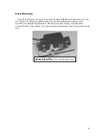
Page 33: ...s for the Ailerons 2 Flaps 2 and Elevators 2 to lie flat within their structures The ServoPro was designed specifically to fill this need and is strongly recommended Contact PCM for more details If you have another method that works for you that will be fine PCM ServoPro servo mounting system 32 ...

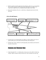
Page 34: ...e pushrod has a straight shot to the control horn It is important that you make sure your geometry of the pushrod is correct A flap unlike an aileron or elevator is not at neutral travel in the center rather it is at the end of its travel in one direction raised and then passes through the mid way point on its way to full deployment Ideally the geometry of the servo arm pushrod and control horn sh...

Page 35: ...el control horn mounted on ply base embedded in wing Control geometry is centered at neutral This drawing is not drawn to scale Beveling allows movement in both directions The aileron servo is mounted similar to the flap servo and is located in its own servo pocket make sure you can run the extension into the wheel and gear bay Imbed the base for the control horn at the appropriate point add the c...

Page 36: ...perfect fit and ensures that the wing will not move rearward under high speed or loads Glue them into their respective locations Tap and drill for the 20 wing bolts at a position as far to the front and side of the ply hold down plate within the fuselage as is possible Final Fuselage Construction The bottom of the forward fuselage can now be sheeted Unlike the wing which will use removable covers ...

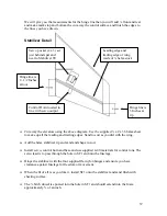
Page 37: ...y voids and sand to satisfaction Stabilizers and Vertical Fins The Stabilizers and Vertical Fins are constructed and finished in an almost identical manner as the main wing Since you now see the process we will just stick to the details and you can use similar methods and materials as before Use the supplied sheets of 1 16th x 4 x 36 balsa to make up the individual skins for the stabilizers and Ve...

Page 38: ...e diagram Use the supplied x 2 x 36 balsa sheet to make up all the leading and trailing edges Sand to suit as you did with the wing Add the balsa stabilizer tip and sand and shape to suit Install servo control horn and base and use supplied 4 40 materials for control runs The servo lead is to pass through the hole in SF1 and into the fuselage Hinge the stabilizer with the four supplied flat nylon ...

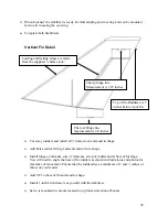
Page 39: ...0 inches Cut away rudders and install all balsa stock and sand to shape Add balsa vertical fin tip and sand entire fin to shape Install hinges and make sure of clearance at top of rudder and at base of fuselage You will need to angle the base of the rudders as shown in illustrations and photos for clearance of movement Ensure that the rudders have a minimum of 1 and inches of throw on your model A...

Page 40: ...poxied into a slot made at the base of the rudders See Photos for details Make up control rods and clevises as before When satisfied with fit and finish you can final sand in preparation for covering The fins can be mounted after covering 39 ...

Page 41: ...nd loop material more commonly referred to as Velcro The use of this material also serves as a convenient method of removing and component that needs replacement or service Typically we will make up a simple mount that has a sufficient amount of Velcro to hold the intended item Then the mount is either glued or screwed into place within the model depending on which method is preferred Rather than ...

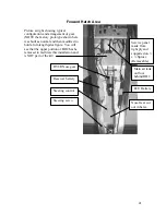
Page 42: ...ed to hold a full length pilot figure You will see that the upper portion of BH2 has be removed to facilitate this installation and is NOT part of the kit DV8R Nose gear Service panel made from light ply and supported on x Spruce Removable Main air tank on floor behind BH2 Receiver battery Steering control Steering servo Nose Gear cut out in balsa ECU Battery 41 ...

Page 43: ...side the motor mounts and up through the fuel tank area to the rear forward hatch No extensions were necessary for the turbine to be installed For a complete list of servos and extension materials see the FAST FACTS sheet supplied with this instruction booklet Holes allow access to screws for Turbine removal Location of rear fuel cell Dubro 50 extends just below rear NACA opening as shown here All...

Page 44: ... control I can While you may have methods of your own we think you should take a look at a few that may new to you and determine if it might be something you want to try GYRO While the DV8R certainly does NOT need a gyro I install one because of the slight benefits it affords me in a variety of conditions simply put in choppy wind conditions a gyro will smooth out the flight of ANY model when prop...

Page 45: ...ls with flap operation Most radios have the ability to put flaps on a knob or dial Also many radios have an available three 3 position switch that is either a dedicated flap switch or one that is available as an auxiliary channels I have found that the three position switch works best for me for many reasons When in flight particularly in the pattern just after take off at slow speed or just befor...

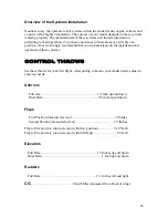
Page 46: ...istance in the installation and operation of these systems CONTROL THROWS Set these throws for your first flight After getting to known your model better adjust to suit your needs Ailerons Full rate 1 2 inch up and down Dual Rate 3 8 inch up and down Flaps First Position measured at root 2 Inches Second Position measured at root 3 5 Inches Flap to Elevator mix down elevator with first position 3 1...

Page 47: ...handling and tracking is great with the DV8R Make sure that the steering is not overly effective and you will have no problems during rollout The prototype weighs 24 5 pounds without fuel With a JetCat P 80 the model needs about 100 feet of pavement or Grass to get airborne when max Performed and can be taken off easily within 200 feet You can use 1st position flap on take off anymore is only incr...

Page 48: ...47 ...

Reviews: