GRL-PCIE5-CEM-RXA User Guide and MOI
Rev7.0
© Granite River Labs 2022 Version 7.0, June 2022. Updated 06.29.2022
Page 24 of 123
4.2.2
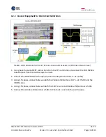
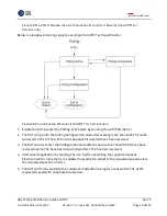
Connect Equipment for Add-In Card Calibration
F
IGURE
12.
R
ECOMMENDED
S
ETUP FOR
TP2
L
ONG
C
HANNEL
R
X
C
ALIBRATION
(PCI
E
G
EN
5
A
DD
-I
N
C
ARD
)
1.
Using back the same BERT connections from the TP3 calibration, disconnect the MU195050A
data outputs from the oscilloscope channels.
2.
Connect the MU195050A data outputs to Variable ISI (Nominal 19.75
–
22.75 dB).
3.
Using 1 ft cables, connect between both the Variable ISI (Nominal 19.75
–
22.75 dB) and the
CBB Rx Lane.
4.
Using 1 ft cables, connect between both the CLB Tx Lane and Variable ISI (Nominal 2.5 dB).
5.
Connect the Variable ISI (Nominal 2.5 dB) to Channels 1 and 3 on the oscilloscope.

