background image


©  PCE Instruments 

22 


Eng

li

s

h


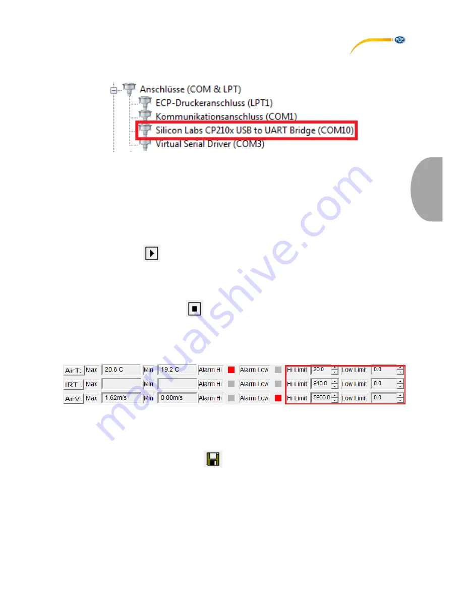
If the device is not identified by the software, make sure that the right COM port is selected. You 
can see the COM port of the device by checking your device manager (Windows Control Panel  
-> Device Manager). 


Click on “COM Port” in the menu bar of the software and select the proper COM port or click on 
“Other COM” and type it in. 
 

Data logger


By using the PC software, you can use the device as a data logger as long as it is connected to 
the PC. To do so, follow these steps: 
 

1. 

Make sure that the device is turned on, connected to the PC and that the proper COM 
port is selected in the software. 

2. 

Click on the 


symbol or on “RealTime(R)” in the menu bar and select “Run”. 

3. 

An input window appears where you can set the sampling time of the logger function. 
Type in the desired time in seconds and press “OK”. 

4. 

The data recording starts. 


To stop the recording, click on the 

 symbol o

r on „RealTime(R)” in the menu bar and select 

“Stop”. 
 

Setting alarm thresholds 

You can use the software to set alarm thresholds. The settings are located below the graph: 


When the reading exceeds or falls below a set threshold level, the square next t

o “Alarm Hi” 

respectively “Alarm Low” begins to flash. 
 

Save Data 

To save the recorded data, click on the 


symbol or click on “File(f)” in the menu bar and 

select “Save”. A save window appears where you can select the file name and the saving 
location. 
The saved data can be viewed with the Windows Text Editor. The saved graphs can be viewed 
with the software. 


Summary of Contents for PCE-VA 11

Page 1: ...eter Bedienungsanleitung User Manual User manuals in various languages fran ais italiano espa ol portugu s nederlands t rk polski can be downloaded here www pce instruments com Letzte nderung last cha...

Page 2: ...1 Technische Spezifikationen 2 2 2 Lieferumfang 2 3 Systembeschreibung 3 3 1 Ger t 3 3 2 Anschl sse 4 3 3 Display 4 3 4 Funktionstasten 5 4 Vorbereitung 6 4 1 Stromversorgung 6 5 Betrieb 7 5 1 Messen...

Page 3: ...ifications 14 2 2 Delivery contents 14 3 System description 15 3 1 Device 15 3 2 Interfaces 16 3 3 Display 16 3 4 Function keys 17 4 Getting started 18 4 1 Power supply 18 5 Operation 18 5 1 Measureme...

Page 4: ...t einem Tuch gereinigt werden Verwenden Sie keine Scheuermittel oder l sungsmittelhaltige Reinigungsmittel Das Ger t darf nur mit dem von der PCE Deutschland GmbH angebotenen Zubeh r oder gleichwertig...

Page 5: ...F C 10 60 C 0 1 C 2 0 C Infrarot Temperatur Einheit Messbereich Aufl sung Genauigkeit F 58 4 F 0 1 F 9 0 F F 4 932 F 0 1 F 2 v MW oder 4 F C 50 20 C 0 1 C 5 0 C C 20 500 C 0 1 C 2 v MW oder 2 F CFM f...

Page 6: ...CE Instruments 3 Deutsch 3 Systembeschreibung 3 1 Ger t 1 Infrarotsensor 2 Anschluss f r Fl gelradsensor 3 Fl gelradsensor mit Lufttemperaturmesser 4 Display 5 USB Schnittstelle 6 Bedienfeld 1 3 2 4 5...

Page 7: ...Anschl sse 1 Anschluss f r Fl gelradsensor 2 Laser Zielhilfe f r Infrarotsensor 3 Infrarotsensor 4 USB Schnittstelle 3 3 Display 1 Anzeige f r Lufttemperatur 2 Anzeige f r Luftgeschwindigkeit Luftmeng...

Page 8: ...en Sie die Taste um im Messmodus den berechneten Durchschnittswert zu betrachten 3 HOLD Dr cken Sie die Taste um den aktuellen Lufttemperaturwert in der oberen Anzeige einzufrieren Dr cken Sie die Tas...

Page 9: ...r Taste zur n chsten Ziffer 8 NEXT AREA Halten Sie die Taste gedr ckt wenn Sie im FLOW Modus sind um in den AREA Modus zu gelangen in dem Sie die Querschnittsfl che einstellen k nnen Halten Sie die Ta...

Page 10: ...Oberfl chentemperatur des anvisierten Objektes zu messen Um das Anvisieren zu erleichtern aktiviert sich automatisch ein Laserpointer ACHTUNG Vermeiden Sie unbedingt Augenkontakt mit dem Laserstrahl...

Page 11: ...kann den Durchschnittswert aus bis zu 20 Einzelmessungen berechnen Um diese Funktion zu nutzen gehen Sie wie folgt vor 1 Schalten Sie das Ger t ein 2 Halten Sie die AVG Taste gedr ckt bis das Ger t zw...

Page 12: ...EXT AREA Taste gedr ckt um die Einstellungen zu best tigen und die ausgew hlte Fl che f r die Messung zu bernehmen Das Messger t kehrt nun in den Messmodus zur ck 5 4 Software 5 4 1 Installation Ger t...

Page 13: ...eisungen auf dem Bildschirm 5 4 2 Benutzung Schalten Sie das Messger t ein verbinden Sie es mit dem PC und starten Sie die Software Sie gelangen nun zum Hauptbildschirm Falls das Messger t nicht erkan...

Page 14: ...ung beginnt Um die Datenaufzeichnung zu stoppen klicken Sie auf das Symbol oder in der Men leiste auf RealTime R und dann auf Stop Alarmgrenzen festlegen Sie k nnen in der Software eigene Alarmgrenzen...

Page 15: ...ichtet Gebrauchte Batterien k nnen unter anderem bei eingerichteten R cknahmestellen oder bei der PCE Deutschland GmbH zur ckgegeben werden Annahmestelle nach BattV PCE Deutschland GmbH Im Langel 4 59...

Page 16: ...hanges to the device The appliance should only be cleaned with a damp cloth Use only pH neutral cleaner no abrasives or solvents The device must only be used with accessories from PCE Instruments or e...

Page 17: ...4 0 F C 10 60 C 0 1 C 2 0 C Infrared temperature Unit Measuring range Resolution Area F 58 4 F 0 1 F 9 0 F F 4 932 F 0 1 F 2 of reading or 4 F C 50 20 C 0 1 C 5 0 C C 20 500 C 0 1 C 2 of reading or 2...

Page 18: ...PCE Instruments 15 English 3 System description 3 1 Device 1 Infrared sensor 2 Vane probe connector 3 Vane probe with air temperature sensor 4 Display 5 USB interface 6 Control panel 1 3 2 4 5 6...

Page 19: ...6 English 3 2 Interfaces 1 Vane probe connector 2 Laser pointer for aiming 3 Infrared sensor 4 USB interface 3 3 Display 1 Display for air temperature 2 Display for air velocity air flow and IR temper...

Page 20: ...average value in measuring mode 3 HOLD Press the key to freeze the current air temperature reading on the upper display Press the key again to unfreeze the upper display Press and hold the key to turn...

Page 21: ...To do so open the battery compartment on the back of the device by using a screwdriver and replace the 9 V battery Close the battery compartment afterwards The device shuts down automatically after an...

Page 22: ...ppears on the bottom of the display 4 The lower display now shows the maximum minimum value since the activation of this mode Continuous average value The device is able to calculate the average value...

Page 23: ...e air temperature To view the maximum or minimum value of the air temperature follow these steps 1 Press the MAX MIN temperature key REC and MAX or MIN appears on the top of the display 2 The upper di...

Page 24: ...CP210xVCPInstaller_x64 exe file if you run a 64 bit operating system or start the CP210xVCPInstaller_x86 exe file if you run a 32 bit operating system If you are not sure which operating system is ins...

Page 25: ...RealTime R in the menu bar and select Run 3 An input window appears where you can set the sampling time of the logger function Type in the desired time in seconds and press OK 4 The data recording st...

Page 26: ...ained pollutants batteries must not be disposed of as household waste They must be given to collection points designed for that purpose In order to comply with the EU directive 2012 19 EU we take our...

Page 27: ...975 114 Fax 1 561 320 9176 Fax 44 0 2380 98703 9 Fax 39 0583 974 824 info pce americas com info industrial needs com info pce italia it www pce instruments com us www pce instruments com english www p...

Page 28: ...Instruments User manuals in various languages fran ais italiano espa ol portugu s nederlands t rk polski can be downloaded here www pce instruments com Specifications are subject to change without no...

Reviews: