background image

Manual 

10 

5.12.3  To operate the software 

5.12.3.1  To open data 


5.12.3.2  Picture analysis 

5.12.3.2.1  Import of the data 

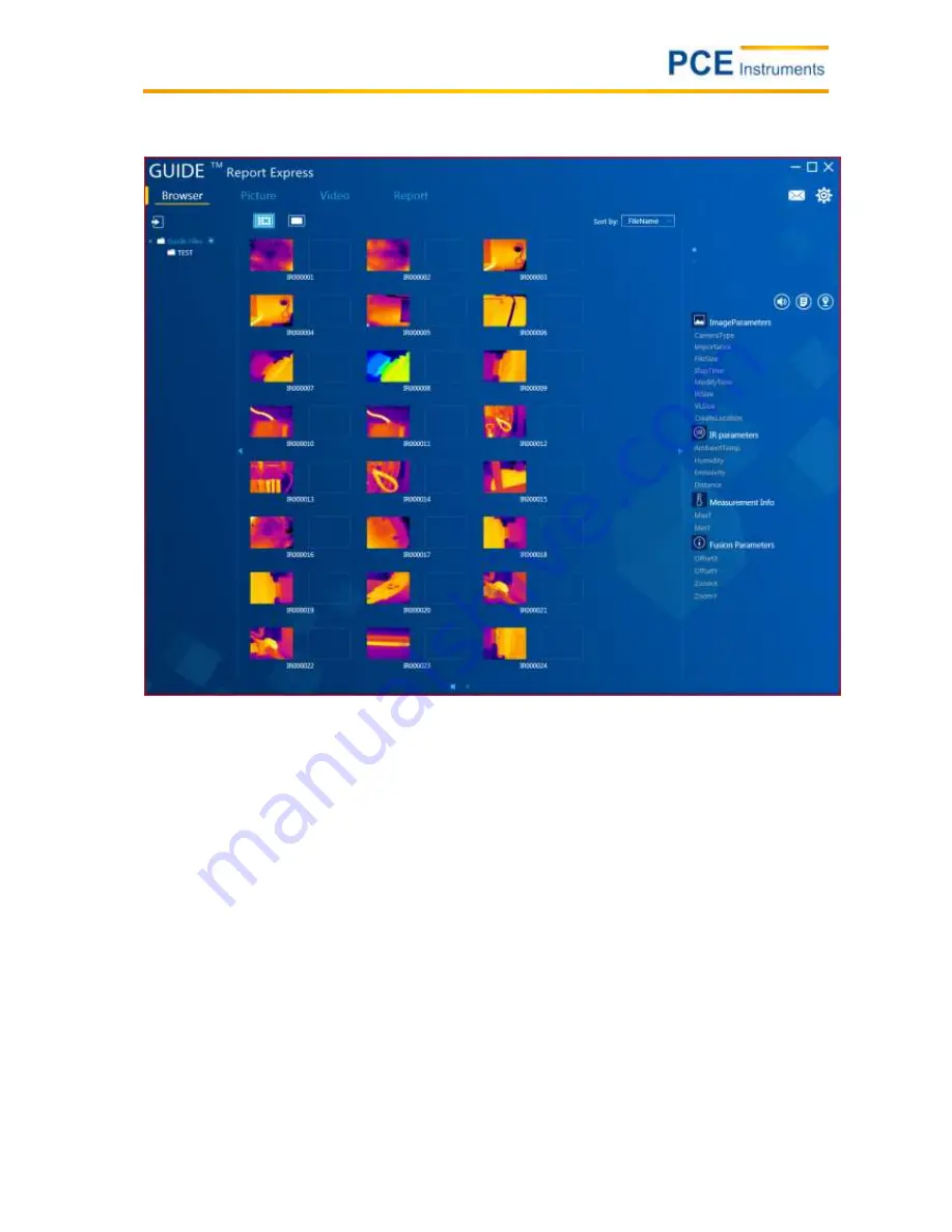
To open the saved thermal images in the software, it is necessary to connect the camera to a computer 
via USB. Your computer 

will then show an additional virtual drive called “GUIDE_IR”. The pictures taken 

by the camera are s

aved under “DCIM” under “PICTURE”: You must then copy the data from that location 

and save them in the folder “Guide Files”. You can find the folder “Guide Files” where you have saved the 
device software on your computer. Start the software then. The pictu

res in the folder “Guide Files” are 

automatically recognised by the software.  

Summary of Contents for PCE-TC 30

Page 1: ...us PCE Instruments UK Ltd Units 12 13 Southpoint Business Park Ensign way Southampton Hampshire United Kingdom SO31 4RF Tel 02380 98703 0 Fax 02380 98703 9 info industrial needs com www pce instrumen...

Page 2: ...common material emissivities 6 5 4 Start up procedure 7 5 5 Display 7 5 6 To save images 7 5 7 Settings 7 5 7 1 Main display 7 5 7 2 Temperature analysis 7 5 7 3 Emissivity setting 7 5 7 4 Palette 8 5...

Page 3: ...ake sure that the device is also protected from splashing water The case must only be opened by qualified personnel of PCE Instruments Otherwise the warranty will become void The instrument should nev...

Page 4: ...Tmin HOLD function Tmax Tmin Display LCD 320 x 240 pixels Thermal sensitivity 80 mK Lens 8 mm Digital zoom 3 x Field of view FOV 18 5 x 18 5 Frequency 50 Hz Working temperature 0 50 C Interface micro...

Page 5: ...Manual 5 4 Device description 4 1 Camera components 4 2 Buttons 4 3 Display...

Page 6: ...harger There is also the possibility to charge the battery via a charger which is however not included in the delivery and can be purchased separately 5 2 Data transfer You can easily transfer your me...

Page 7: ...by selecting with the and buttons By pushing the select button again you can select the appropriate adjustment range and use the sub menus in the same way as the main menu The following sub menus are...

Page 8: ...or this purpose the auto mode and the lock mode factory default setting If lock mode is on the scale has fixed extremes In auto mode the limits are variable and adapt to their environment 5 10 To disp...

Page 9: ...tware configuration 5 12 2 1 Hardware configuration minimum requirements Requirement Details CPU Pentium 4 2 4 GHz RAM 512 MB and more Graphic card NVIDIA GeForce 5200 125 MB Hard disc 40 GB and more...

Page 10: ...our computer will then show an additional virtual drive called GUIDE_IR The pictures taken by the camera are saved under DCIM under PICTURE You must then copy the data from that location and save them...

Page 11: ...to create the folder You can create a subfolder under each folder 5 12 3 2 3 To delete folders Click to select the folder to be deleted The symbols and appear next to the folder When you click on you...

Page 12: ...12 3 2 5 Note on commented images In case you see a in connection with the image properties this means that there is a comment along with the selected image If the selected image comes with a this me...

Page 13: ...n the picture you would like to select 2 If an image has already been loaded you can click on to choose another one 3 Select an image in normal mode and pull it to the analysis interface with the mous...

Page 14: ...analysis tools You have the possibility to add analysis tools to the image by means of the software To add spots Click on The spot will then be displayed like this To add lines Click on The line will...

Page 15: ...ick on The dashed line will be displayed like this Rectangle Click on The rectangle will be displayed like this Circle Click on The circle will be displayed like this Polygon Click on The polygon will...

Page 16: ...e dimensional display When you click on the image is displayed three dimensionally This makes it possible for you to turn it by means of the mouse You can also increase or decrease the size of the ima...

Page 17: ...mits are restored Click on to save the colour palette as you have set it 5 12 3 3 5 Emissivity You can choose a value from the analysis information which you have to double click on Then a new window...

Page 18: ...Manual 18 5 12 3 4 Report creation...

Page 19: ...as an infrared image as well as a normal image 5 12 3 4 2 To add letters The user can easily make changes to the template adds texts fields to the template adds a comment to the template adds a highli...

Page 20: ...pen the template database You can create a new template by clicking on You can delete it by clicking on The template currently used is highlighted in green 5 12 3 4 5 To export reports By clicking on...

Page 21: ...and Chinese as software language 5 12 3 5 2 Units The software offers the possibility to adjust temperature and length units in line with user needs and purposes As temperature units you can choose b...

Page 22: ...in what way You can select either both extremes the maximum temperature the minimum temperature or none 5 12 3 5 4 Report Here you can make a standard setting of what is to be shown in the report You...

Page 23: ...Manual 23 5 12 3 5 5 Others Further settings regarding updates and popup windows can be adjusted here...

Page 24: ...ents All products are CE and RoHs approved 7 Contact If you have any questions about our range of products or measuring instruments please contact PCE Instruments 7 1 PCE Instruments UK By post PCE In...

Reviews: