


PCB Load & Torque, Inc.
Toll-Free in USA 866-684-7107
716-684-0001
www.pcbloadtorque.com
DUAL BRIDGE LOAD CELL OPERATION MANUAL
1
TABLE OF CONTENTS
1.0 INTRODUCTION.................................................................................................................. 2
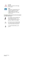
2.0 SAFETY PRECAUTIONS .................................................................................................... 2
3.0 OVERVIEW .......................................................................................................................... 2
3.1 Dimensions .......................................................................................................................................2
3.2 Standard Components ......................................................................................................................3
3.3 Optional Components .......................................................................................................................3
4.0 MECHANICAL INSTALLATION .......................................................................................... 3
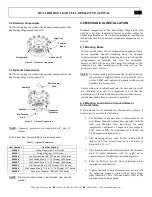
4.1 Mounting Bases ................................................................................................................................3
4.2 Mounting Load Cell to a Standard Base or Custom Fixture .............................................................3
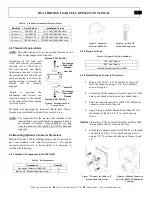
4.3 Threaded Tension Rods....................................................................................................................4
4.4 Mounting Optional Connector Protectors..........................................................................................4
4.4.1 Included Components in Kit (084A90)...................................................................................4
4.4.2 Required Tools........................................................................................................................4
4.4.3 Installation of Connector Protector .........................................................................................4
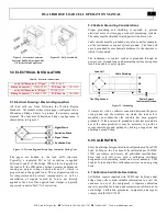
5.0 ELECTRICAL INSTALLATION ........................................................................................... 5
5.1 Electrical Drawing / Western Regional Std. ......................................................................................5
5.2 Cable & Grounding Considerations ..................................................................................................5
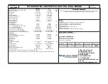
6.0 CALIBRATION..................................................................................................................... 5
6.1 Calibration Certificate Description.....................................................................................................5
6.1.1 Measured Output.....................................................................................................................6
6.1.2 Hysteresis................................................................................................................................6
6.1.3 Best Fit Output ........................................................................................................................6
6.1.4 Strain Gage Measurements .....................................................................................................6
6.1.5 Shunt Calibration Standard Resistor .......................................................................................6
6.1.6 Static Error Band (SEB)..........................................................................................................6
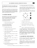
7.0 MOMENT COMPENSATION ............................................................................................... 6
8.0 FATIGUE & OVERLOAD..................................................................................................... 6
9.0 SHUNT CALIBRATION DESCRIPTION.............................................................................. 7
9.1 Resistor Value ...................................................................................................................................7
9.2 Shunt Calibration Process.................................................................................................................7
9.3 Estimating Shunt Resistor for a Given Load .....................................................................................7
10.0 MAINTENANCE................................................................................................................. 7
11.0 TROUBLE SHOOTING ...................................................................................................... 8
11.1 Mechanical Trouble Shooting .........................................................................................................8
11.2 Electrical Trouble Shooting .............................................................................................................8
11.2.1 Estimating Bridge Balance using an Ohm Meter ..................................................................8
12.0 CALIBRATION / REPAIR SERVICES ............................................................................... 8
12.1 RMA / Purchase Order....................................................................................................................9
13.0 WARRANTY ...................................................................................................................... 9


