


BALLISTICS PRESSURE TRANSDUCER MODELS 165B02 AND 118A07 OPERATION MANUAL
3
Selected Values for 77°F (25°C)
Measured resonant frequencies may differ slightly from
the chart values due to variations in the velocity of
sound in the air from changes in temperature and
pressure of the air in the passage.
If possible, keep passage lengths below 0.10 inches
(.254 mm) for best results in most ballistic applications,
especially at the casemouth and when measuring port
pressures.
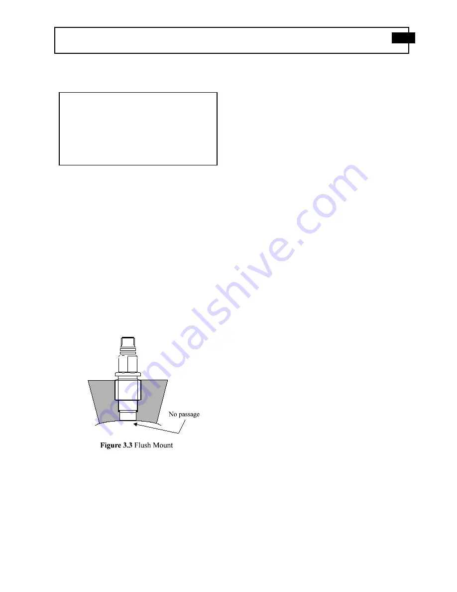
3.4
Flush Mount
The flush mount installation is intended for tangential
shot shell pressure measurement and there is no reduced
area passage from the sensor diaphragm to the test
chamber. Instead, the sensor diaphragm is mounted flush
with, or slightly recessed from, the inside surface of the
test chamber. See Figure 3.3.
If thermal transients or diaphragm impingement are
concerns, use the flush mount technique only when
space or rise time considerations preclude the use of the
recess mount installation.
3.5
Flash Thermal Protection
Additional steps may be taken to provide protection
from flash thermal effects. The sensor diaphragm may
be thermally insulated with DC-4 silicone grease or its
equivalent. In place of the silicone rubber, one layer of
black vinyl electrical tape on the diaphragm may provide
sufficient insulation.
3.6
Cable Installation
Use only low-noise treated coaxial cable (PCB Model
003A or equivalent) to connect the transducer to the
charge amplifier, in-line voltage amplifier, or other high
input impedance readout instrument. For further details
on such cabling contact PCB.
Protect the ultra high impedance connection against
moisture contamination with shrink tubing or other
suitable method. Figures 5.1 and 5.2 illustrate typical
circuit connections.
It is advisable to support transducer cables by tying them
to rigid structures to prevent excessive motion that can
generate noise and materially shorten cable life. Allow
adequate strain relief.
4.0
CALIBRATION
This transducer can be calibrated using either static
hydraulic techniques, such as by a dead weight tester, or
by comparison with a standard dial gauge.
Set the charge amplifier for a long time constant, and
allow the transducer to thermally stabilize before
attempting to calibrate it.
Passage
Passage
Approx. fastest
length
resonance
pulse rise time
(inches)
(kHz)
(microseconds)
.050
66
5
.100
33
10
.200
16.5
20
.50
6.6
50
1.0
3.3
100
Drawing Number: 21109
Revision: NR


