ICP
FORCE SENSOR OPERATION MANUAL
3
Figure 5 - Series 208 General Purpose and Axial
Connector ICP
®
Force Sensor Installation Methods
LINKS
Series 221B to 227C ICP
Link Sensors are designed for
measuring compression from a few pounds(N) to 50,000 lbs (to
222.4 kN), and tension forces from a few pounds (N) to 30,000
lbs (to 133.4 kN). A link consists of a standard PCB ring sensor
preloaded between two hex end nuts. All hex nuts are internally
threaded for mounting ease to a customer test structure. Unlike
ring design sensors, additional external preloading is not
required as the factory installed external mounting hardware
places the sensor in a preloaded state.
The hex nuts do not loosen naturally.
DO NOT ADJUST THE
NUTS WITH A WRENCH.
Loosening or tightening of the
hex nuts will change the preload applied to the sensor. The
result is that the sensor output will no longer match the factory
supplied calibration certificate. In the unlikely event the
mounting hardware becomes loose, contact PCB’s service and
repair document for proper instructions for returning the sensor
to PCB for recalibration..
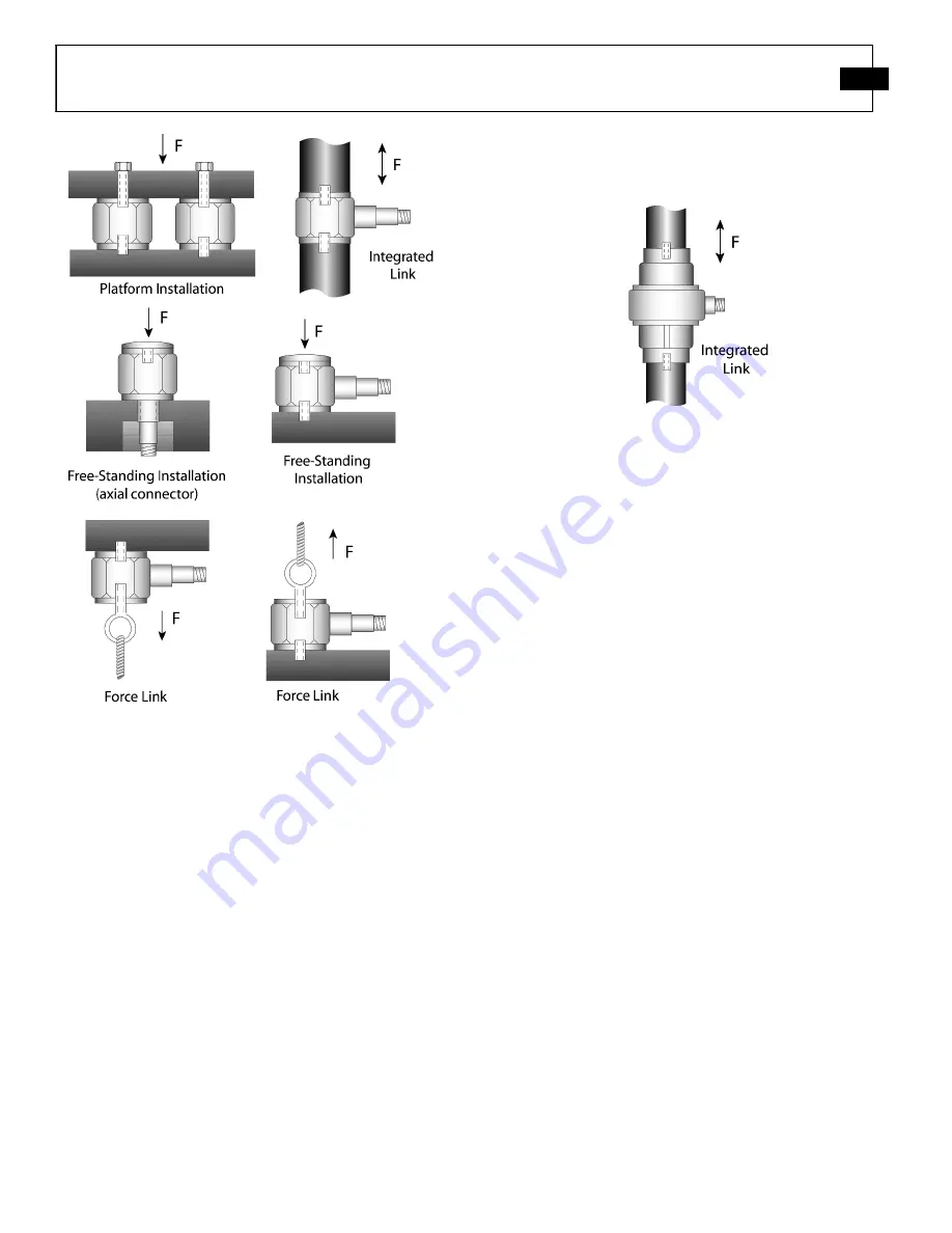
Figure 6 outlines some possible mounting configurations of the
link series of sensors.
Figure 6 – Series 221 to 227 ICP
®
Force Link Sensor
Mounting Method
3- COMPONENT TRIAX SENSORS
PCB’s line of 3-Component force sensors is capable of
simultaneously measuring force in three (3) orthogonal
directions (X, Y, and Z). Internally, three sets of quartz crystals
are cut, oriented and preloaded so the maximum output from
the crystal cut for the specific plane is obtained when a force is
applied axially to the specific x, y or z plane. Sensor output
from
loads
applied
in
the
alternate,
transverse
planes(considered channel cross-talk) is negligible as the
crystal sets are cut for maximum output in a specific plane.
Optimum performance and linear operation of 3-component
force sensors is obtained when a preload is applied to the sensor.
Versions are available with ranges up to 10K lb (45kN) in the
Z-axis (perpendicular to the top surface), and up to 4,000 lbs
(18kN) in the X and Y (shear) axes.
There are two modes of triaxial force sensors.
ICP
triaxial
designs utilize built-in microelectronic circuitry that provides a
low-impedance voltage, the electrical output of which is passed
to external signal conditioning via one multi-pin connector
mounted on the sensor housing This design mechanically has
one 4-pin electrical connector that may be coupled to a single
multi-conductor sensor cable.
High impedance
charge mode models contain three (3)
separate electrical output connectors on the sensor housing,
each corresponding to the respective x, y, or z axis. Low noise
cables should be used in low impedance system arrangements.
These models are ideal for use in harsh industrial or high
temperature environments.
Figure 7 outlines installation possibilities of triax force sensors.
Summary of Contents for M209C02
Page 17: ......


