Drawing Number: 21210 Revision: NR
AN IMPROVED TECHNIQUE FOR
UTILIZATION OF CONFORMAL BALLISTICS
SENSOR CALIBRATION DATA
7
* Adds offset pressure (not available from PCB).
+-
Page 1: ...PRESSURE SENSOR Installation and Operating Manual For assistance with the operation of this product contact PCB Piezotronics Inc Toll free 800 828 8840 24 hour SensorLine 716 684 0001 Fax 716 684 0987 E mail info pcb com Web www pcb com ...
Page 2: ...ialized tests including sensitivity at elevated or cryogenic temperatures phase response extended high or low frequency response extended range leak testing hydrostatic pressure testing and others For more information contact your local PCB Piezotronics distributor sales representative or factory customer service representative Returning Equipment If factory repair is required our representatives ...
Page 3: ...ation on particular operating steps The following symbols may be found on the equipment described in this manual This symbol on the unit indicates that high voltage may be present Use standard safety precautions to avoid personal contact with this voltage This symbol on the unit indicates that the user should refer to the operating instructions located in the manual This symbol indicates safety ea...
Page 4: ...E 住房 O O O O O O PCB板 X O O O O O 电气连接器 O O O O O O 压电晶体 X O O O O O 环氧 O O O O O O 铁氟龙 O O O O O O 电子 O O O O O O 厚膜基板 O O X O O O 电线 O O O O O O 电缆 X O O O O O 塑料 O O O O O O 焊接 X O O O O O 铜合金 黄铜 X O O O O O 本表格依据 SJ T 11364 的规定编制 O 表示该有害物质在该部件所有均质材料中的含量均在 GB T 26572 规定的限量要求以下 X 表示该有害物质至少在该部件的某一均质材料中的含量超出 GB T 26572 规定的限量要求 铅是欧洲RoHS指令2011 65 EU附件三和附件四目前由于允许的豁免 CHINA RoHS COMPLIANCE ...
Page 5: ... O Wires O O O O O O Cables X O O O O O Plastic O O O O O O Solder X O O O O O Copper Alloy Brass X O O O O O This table is prepared in accordance with the provisions of SJ T 11364 O Indicates that said hazardous substance contained in all of the homogeneous materials for this part is below the limit requirement of GB T 26572 X Indicates that said hazardous substance contained in at least one of t...
Page 6: ...ngement allows for tolerance in the location of the guide pin hole in an axial direction on the test barrel or calibration adaptor The precise depth adjustment is obtained by the use of the correct thickness spacer selected from a set of 9 spacers of various thicknesses supplied with each sensor Once the proper thickness spacer is found removal and re installation now becomes a routine matter 3 0 ...
Page 7: ...ect a thinner spacer and remount Once the proper thickness is found for perfect flushness the sensor may be removed and reinstalled using this same spacer and the proper depth will be achieved each time NOTE For best accuracy of results use same charge amplifier for calibration and for actual operation Use long TC for calibration medium or short TC for best drift free operation 4 0 POLARITY Polari...
Page 8: ...r to allow easy insertion and extraction the case must be expanded slightly by the internal pressure before force can be transmitted to the sensor See the enclosed guide An Improved Technique for Utilization of Conformal Ballistics Sensor Calibration Data for methods of dealing with this topic 6 0 MAINTENANCE It is essential for normal operation of the Model 117B that the insulation resistance be ...
Page 9: ...Drawing Number 21086 Revision NR OPERATION MANUAL FOR CONFORMAL BALLISTICS PRESSURE SENSOR Series 117B 4 ...
Page 10: ...Drawing Number 21086 Revision NR OPERATION MANUAL FOR CONFORMAL BALLISTICS PRESSURE SENSOR Series 117B 5 ...
Page 11: ...mmunition under test to take into account transmissibility characteristics of the cartridge case for each lot of ammunition Because a certain amount of pressure is required to fully obturate the cartridge case in the test chamber a rather severe non linearity is exhibited over the first several thousand psi of input pressure i e until the cartridge case is pressed firmly against the inside chamber...
Page 12: ...or two percent of full scale is specified for quartz sensors An acceptable instrument is then defined as one whose data points all fall within this error band The sensitivity of an instrument so calibrated is simply the full scale output charge or voltage divided by full scale input pressure where F S output is determined by the straight line as defined above input S F output S F y Sensitivit Eq 1...
Page 13: ...ance between the cartridge case and the chamber wall Obturation of the cartridge occurs in this region However when obturation is complete the sensor output is then linear with pressure from this point up to maximum rated pressure In the past a common procedure has been to calibrate the conformal at the expected nominal pressure deriving a sensitivity at this point e g point Po Qo in figure 4 The ...
Page 14: ...he data from 20 consecutive calibration runs performed on a conformal sensor yielded a slope of 04 pC psi and an intercept of 7 500 psi determined by constructing the best fitting straight line as described previously Assume also that average expected peak pressure is 25 000 psi Approximate full scale charge output is pC 1000 pC psi 04 psi 25 000 Set range of charge amplifier output to 1000 pC vol...
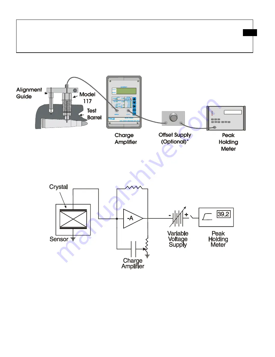
Page 15: ... can be further refined to include a variable voltage source as a bias in series with the output of the charge amplifier This voltage bias can be set to simulate the offset pressure and then the true peak pressure can be read directly See figure 6 on the next page Example Assume a 20 round calibration lot and attendant graph yield a slope of 250 pC psi and an offset of 5 000 psi Proceed as follows...
Page 16: ...scale pressure to find full scale picocoulombs 40 000 psi x 250 pC psi 10 000 pC Set the charge calibrator for 10 000 pC and apply this signal to the input of the amplifier Now adjust the gain of the oscilloscope or charge amplifier if gain adjust is available to make full scale equal to a selected number of oscilloscope divisions For example 6 Div 40 000 psi Now the peak value can be determined f...
Page 17: ...Drawing Number 21210 Revision NR AN IMPROVED TECHNIQUE FOR UTILIZATION OF CONFORMAL BALLISTICS SENSOR CALIBRATION DATA 7 Adds offset pressure not available from PCB ...
Page 18: ...xy Epoxy Electrical Connector 10 32 Coaxial Jack 10 32 Coaxial Jack Weight 0 45 oz 13 gm All specifications are at room temperature unless otherwise specified In the interest of constant product improvement we reserve the right to change specifications without notice ICP is a registered trademark of PCB Group Inc OPTIONAL VERSIONS Optional versions have identical specifications and accessories as ...
Page 19: ...TE 065A19 NOTE 50698 250 6 35 46 11 8 89 22 7 1 63 41 4 10 32 UNF 2A CO AXIAL ELECTRICAL CONNECTOR 224 5 69 ALIGNMENT GUIDE MODEL 045B 750 19 05 500 12 70 187 4 74 250 6 35 565 025 14 35 64 LOCATE YELLOW DOT TOWARD CASE MOUTH ALIGNMENT HOLE MAY BE LOCATED EITHER FORE OR AFT OF SENSOR MOUNTING HOLE MOUNTING TORQUE ON 315 8 00 HEX 5 10 FT LBS 6 8 13 6 NEWTON METERS CENTERLINE OF 2500 6 350 HOLE MUST...