3
ICP
3-COMPONENT FORCE LINK OPERATION MANUAL
The condition of the mating surfaces can adversely
affect the sensitivity of the sensor. It is essential that all
surfaces be clean
,
rigid and perfectly flat to avoid
erroneous data. A good mating surface may be obtained
by lapping
,
turning, spot-facing, or surface grinding.
Surface flatness should be held to within 0.001 (TIR)
over the entire mating surface. The protective cap
should remain on the connector during installation to
prevent contamination or damage.
A light coating of silicon grease (DC-4 or equivalent) on
the mating surface enhances the coupling between the
mounting base and mounting surface and provides the
best high-frequency response.
Connect one end of the interconnect cable to the sensor
connector and the other end to the XDCR jack on the
signal conditioner. Make sure to tighten the cable
connector to the sensor. DO NOT spin the sensor onto
the cable, as this fatigues the cable pins, resulting in a
shorted signal and a damaged cable.
For installation in dirty, humid, or rugged environments,
it is suggested that the connection be shielded against
dust or moisture with shrink tubing or other protective
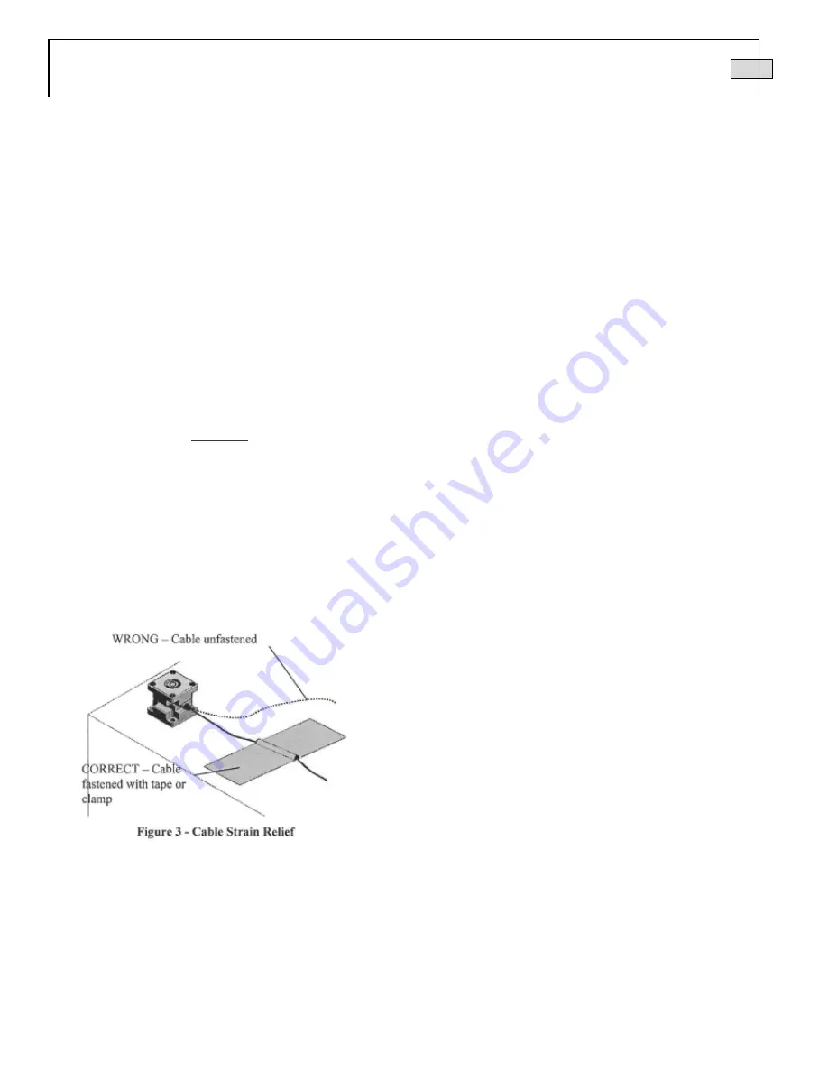
material. Strain relieving the cable/sensor connection
can also prolong cable life. Mounting cables to a test
structure with tape, clamps, or adhesives minimizes
cable whip. See
Figure 3.
4.0 OPERATION
ICP
®
force link sensors require a constant-current
excitation voltage for operation. The enclosed
specification sheet provides specific power
requirements. Required supply voltage is normally 20 to
30 VDC, while the constant current required ranges
from 2 to 20 mA
.
PCB standard battery-powered signal conditioners are
factory set at 2
mA
and may be used to adequately drive
a signal for 100 feet. PCB line signal supplies are
factory set at 4
mA
(and adjustable from 2 to 20
mA),
enabling signals to be transmitted over hundreds of feet.
It
is necessary to supply the sensor with a 2 to 20 mA
constant current at +20 to +30 VDC through a current-
regulating diode or equivalent circuit, contained in all
PCB signal conditioners. See Guide G-000IE for
powering and signal conditioning information pertaining
to all ICP
®
instrumentation.
Most of the signal conditioners manufactured by PCB
have an adjustable current feature allowing a choice of
input currents from 2 to 20
mA.
In general, for lowest
noise (best resolution), choose the lower current ranges.
When driving long cables (to several thousand feet), use
The higher current, up to 20
mA
maximum. Consult the
factory to determine if higher current settings are
required.
Operation requires the connection of the force sensor
first to a signal conditioner, then to a readout device
(oscilloscope, meter, recorder, or A-to-D board) or to a
readout device with built-in ICP® sensor excitation
.
Tighten the cable to the sensor by hand to ensure good
electrical contact.
5.0 POLARITY
Compressive forces upon an ICP® 3-component force
link produce a positive-going voltage output. Tensile
forces produce a negative-going voltage output. Sensors
with reversed polarity are available upon request.
6.0 LOW-FREQUENCY MONITORING
Force link sensors used for applications in short term,
steady state monitoring, such as sensor calibration, or
short term, quasistatic testing should be powered by
signal conditioners that operate in DC-coupled mode.
PCB Series 484 Signal Conditioner operates in either
AC or DC-coupled mode and may be supplied with gain


