


REACTION TORQUE SENSOR OPERATION MANUAL
4
4.0 ELECTRICAL INSTALLATION
For proper electrical connections, refer to the
installation drawing for the torque sensor, and the
wiring drawing for the signal conditioner used.
Construct the interconnect cable from high-quality
shielded instrumentation cable. Various cable
assemblies are available through PCB.
Connect one end of the cable to the sensor
connector and the other end to the signal
conditioner. Make sure to tighten the cable
connector to the sensor. For installation in dirty,
humid, or rugged environments, it is suggested that
the connection be shielded against dust or moisture
with shrink tubing or other protective material.
Strain relieving the cable/sensor connection can also
prolong cable life. Mounting cables to a test
structure with tape, clamps, or adhesives minimizes
cable whip.
5.0 POLARITY
Clockwise torque upon standard PCB reaction
torque sensors produces a positive-going voltage
output. Counter-clockwise torque produces a
negative-going voltage output.
6.0 SHUNT CALIBRATION
Shunt calibration is the known, electrical,
unbalancing of a strain gage bridge by means of a
fixed resistor that is placed, or
“
shunted
”
, across
one leg of the bridge. The
“
Wheatstone Bridge
”
utilized by PCB reaction torque sensors are typically
calibrated using the shunt calibration technique.
Shunt calibration is a method of periodically
checking the gain or span of a signal conditioner,
which is used in conjunction with a strain gage
based transducer, without exposing the transducer to
known, traceable, physical input values. If required,
adjustments can then be made to the signal
conditioner to insure accurate measurement results.
The strain gage bridge is
“
in balance
”
when the host
mechanical structure is unloaded and unstressed.
As the host structure (diaphragm, bending beam,
shear beam, column, etc.) is loaded or stressed, the
Wheatstone Bridge becomes unbalanced, resulting
in an output signal that is proportional to the applied
load.
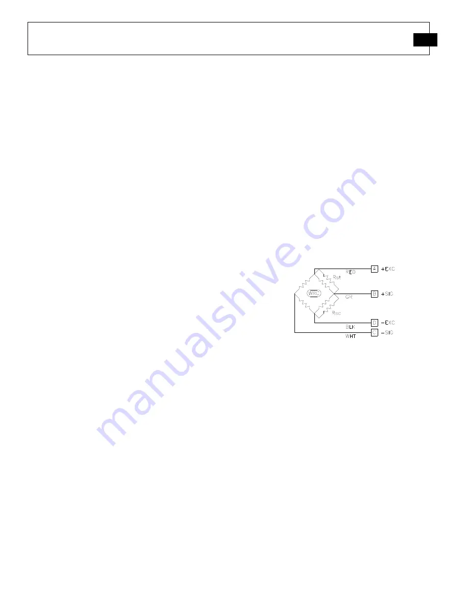
Shunt calibration simulates the mechanical input to
a transducer by unbalancing the bridge with a fixed
resistor placed across, or in parallel with, one leg of
the bridge. For tension shunt calibration, or +CAL,
the shunt resistor (R
st
) is shunted across the
+Excitation (A) and +Signal (B) leg of the bridge.
For compression shunt calibration, or
–
CAL, the
shunt resistor (R
sc
) is shunted across the -Excitation
(D) and +Signal (B) leg of the bridge. Refer to
Figure 6
for shunt resistor locations in the
Wheatstone Bridge circuit.
Figure 6 - Shunt Resistor Locations
Shunt Calibration Procedure
1. Connect the transducer to an appropriate strain
gage signal conditioner and allow adequate time
for the system to stabilize.
2. Apply
a
full-scale,
N.I.S.T.
traceable,
mechanical input (or torque) to the transducer.
3. Adjust the signal conditioner
’
s gain or span
controls, as required, to obtain a full-scale
electrical output signal, and/or numeric display
that represents the applied, mechanical input
quantity.
4. Remove the mechanical input (or torque).
5. Place the shunt calibration resistor across an
appropriate leg of the Wheatstone Bridge as
discussed above.