background image

6

Technical Reference Booklet

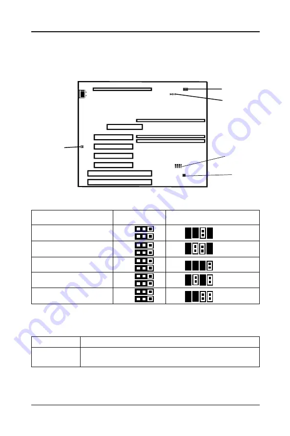
Jumper Settings

This chapter explains how to configure the motherboard’s hardware. Before
using your computer, make sure all jumpers and DRAM modules are set
correctly. Refer to this chapter whenever in doubt.

JP5, JP6, JP7 - CPU Type Selection

CPU Type and Speed

JP5

JP7

JP6

Pentium II - 200MHz

Pentium II - 233MHz

Pentium II - 266MHz

Pentium II - 300MHz

Pentium II - 333MHz

JP2 - AUTO CPU Core-Voltage Selection (All open)

JP4 - CMOS Clear

JP4

Selection

2-3

CMOS Clear

1-2

Normal (default)

JP8, JP15 - PNP BIOS Program Voltage

JP8&JP15 are pre-installed in the factory. They should NOT be altered by
the users.

JP15

JP8

JP12

JP4

JP2

JP7

JP5
JP6

1
1
1

1

1

1
1
1
1
1

1
2
1
2

1
2
1
2
1
2

Summary of Contents for 35880101

Page 1: ...BETWEEN THE EQUIPMENT AND THE RECEIVER CONNECTTHEEQUIPMENTINTOANOUTLETONACIRCUITDIFFERENTFROM THATOFTHERECEIVER CONSULTTHEDEALERORANEXPERIENCEDAUDIO TELEVISIONTECHNICIAN NOTE Connecting this device to...

Page 2: ...Program Voltage 6 Memory Configuration 7 Installation 8 Installing the Retention Mechanism 8 Installing the Processor 8 Installing the Spacer 9 Installing a DRAM Module 9 BIOS SETUP 1 0 Starting Setu...

Page 3: ...56KB or 512K System Memory Up to 384MB SDRAM or 768MB EDO A total of three 168 pin DIMM sockets 3 3V EDO Synchronous DRAM Supports 3 3V Extended Data Output EDO DRAM at 50 and 60ns speed and Synchrono...

Page 4: ...lay for DOS Windows 3 X as well as Windows 95 Fully steerable PCI interrupts Power Management Supports SMM APM and ACPI Break switch for instant suspend resume on system operation Energy star Green PC...

Page 5: ...5 Hardware Setup Motherboard Layout Model Code No 35880101 The following diagrams show the relative positions of the jumpers connectors major components and banks on the motherboard...

Page 6: ...JP7 CPU Type Selection CPU Type and Speed JP5 JP7 JP6 Pentium II 200MHz Pentium II 233MHz Pentium II 266MHz Pentium II 300MHz Pentium II 333MHz JP2 AUTO CPU Core Voltage Selection All open JP4 CMOS C...

Page 7: ...by the edges remove it from its antistatic package 4 Make sure the clips at either end of the socket are pushed away from the socket 5 Position the DIMM above the socket Align the two small notches in...

Page 8: ...ttachment studs 4 To secure the mechanism tighten the captive nuts Installing the Processor To install the processor follow these steps 1 Insert the processor in the retention mechanism 2 Press down o...

Page 9: ...e that a DRAM module has a polarity notch at one end so that it fits into a socket only one way Hold the module by the edges Do not touch the shiny contacts Align the DRAM module edge connector with t...

Page 10: ...owing message appears briefly at the bottom of the screen during the POST Power On Self Test Hit DEL if you want to run SETUP If the message disappears before you can respond and you still wish to ent...

Page 11: ...tup For Configuring PCI Plug Play features Peripheral Setup For Configuring peripheral features CPU configuration Setup For Configuring CPU configuration features Auto Detect Hard Disks For auto detec...

Page 12: ...s identify the types of the two channels that have Pri Slave been installed in the computer There are 46 predefined types and Sec Master four user definable types in BIOS Type 1 to Type 46 are predefi...

Page 13: ...yboard operation shadowing and security Advanced Chipset Setup The Chipset Features Setup option is used to change the values of the chipset registers These registers control most of the system option...

Page 14: ...lear the previously entered password from the CMOS memory You will be asked to confirm the password Type the password again and press Enter You may also press Esc to abort the selection and operate wi...

Page 15: ...IFLASH COM to the diskette 2 Allow the PC system to boot from the DOS diskette 3 At the DOS prompt key in AMIFLASH COM and hit ENTER 4 The question Save Existing BIOS is displayed Key in N if there is...

Reviews: