4
A07691
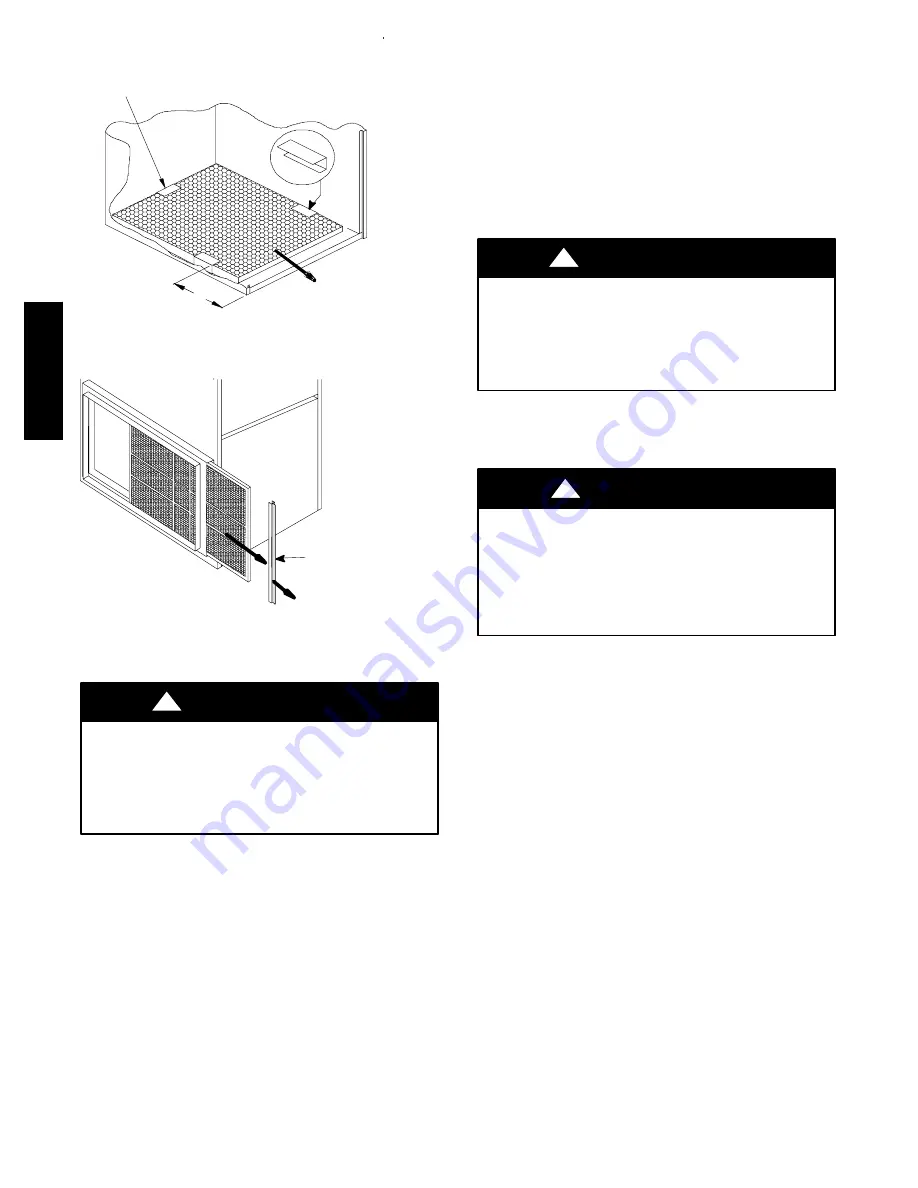
Center Clip
side-to-side
9”
(228.6 mm)
Fig. 2 -- Bottom Filter Arrangement
A07690
Filter Rack
End Cap
Fig. 3 -- Filter Installed for Side Inlet
f. Remove blower wheel from housing.
UNIT DAMAGE HAZARD
Failure to follow this caution may result in furnace component
failure.
The blower wheel should not be dropped or bent as balance
will be affected.
CAUTION
!
g. Clean wheel per instructions on degreaser cleaner. Do
not get degreaser cleaner in motor.
9. Reassemble motor and blower wheel by reversing items 8b
through 8f. Ensure wheel is positioned for proper rotation.
Be sure to reattach ground wire. Tighten setscrew to 140 to
160 in.--lb torque.
10. Reinstall blower assembly in furnace.
11. Reinstall control box, transformer, and door switch
assembly on blower shelf.
12. Reinstall condensate trap and tubing if previously removed.
a. Reinstall condensate trap in hole in blower shelf.
b. Connect condensate trap drain tubes. See Fig. 6, 7, or 8.
NOTE
: Ensure tubes are not kinked or pinched, as this will
affect operation.
c. Connect field drain to condensate trap.
13. Reconnect wires.
Refer to furnace wiring diagram, and connect thermostat leads if
previously disconnected. (See Fig. 18.)
UNIT DAMAGE HAZARD
Failure to follow this caution may result in unit component
damage.
Heating speed selection MUST be adjusted to provide proper
temperature rise as specified on the rating plate.
CAUTION
!
14. Turn on electrical supply. Manually close blower access
door switch. Use a piece of tape to hold switch closed.
Check for proper rotation by jumpering R to G.
ELECTRICAL SHOCK HAZARD
Failure to follow this warning could result in personal injury
or death.
Blower access door switch opens 115-v power to furnace
control. No component operation can occur. Caution must be
taken when manually closing this switch for service purposes.
!
WARNING
15. If furnace is operating properly, remove tape to release
blower access door switch, remove jumper across R to G,
and replace blower access door.
Procedure 3 — Cleaning Burners
The following items should be performed by a qualified service
technician. If burners develop an accumulation of light dirt or dust,
they may be cleaned by using the following procedure:
1. Turn off gas and electrical supplies to furnace.
2. Remove main furnace door.
3. Using backup wrench, disconnect gas supply pipe from
furnace gas control valve.
PG
9M
TA
V
Summary of Contents for PG9MTAV
Page 6: ...6 A07706 Fig 6 Upload Installations Top Vent PG9MTAV ...
Page 7: ...7 A07707 A07707 Fig 7 Upload Installations Vent Through Left Side PG9MTAV ...
Page 8: ...8 A07708 Fig 8 All Models Vent Through Right Side PG9MTAV ...
Page 9: ...9 A07829 Fig 9 Downflow Left Side Vent and Trap PG9MTAV ...
Page 10: ...10 A07830 Fig 10 Downflow Right Side Vent and Trap PG9MTAV ...
Page 11: ...11 A07709 Fig 11 Horizontal Left Through Top PG9MTAV ...
Page 12: ...12 A07710 Fig 12 Horizontal Left Side Vent PG9MTAV ...
Page 13: ...13 A07711 Fig 13 Horizontal Right Through Top PG9MTAV ...
Page 14: ...14 A07712 Fig 14 Horizontal Right Side Vent PG9MTAV ...
Page 20: ...20 A07822 Fig 20 Wiring Diagram PG9MTAV ...


