11
COMBUSTION AIR AND VENT SYSTEM
CARBON MONOXIDE POISONING HAZARD
Failure to follow this warning could result in personal injury
or death.
If holes are found or if the vent pipe is obstructed or is not
connected, toxic fumes can escape into your home. DO NOT
OPERATE YOUR FURNACE. Call your dealer for service.
!
WARNING
UNIT OPERATION HAZARD
Failure to follow this caution may result in intermittent unit
operation.
For proper and safe operation the furnace needs air for
combustion and ventilation. Do not block or obstruct air
openings on the furnace, air opening to the area in which the
furnace is installed, and the space around the furnace.
CAUTION
!
Visually inspect the combustion area and vent system before each
heating season. Make sure that all PVC pipes leading into the
combustion area and vent are free from any cracks and sags. An
accumulation of dirt, soot, or rust can mean a loss of efficiency and
improper performance. Buildups on the main burners can cause
faulty firing. This “delayed ignition” is characterized by an
alarmingly loud sound.
Check the combustion- air intake adjacent to the furnace or outside
your home for blockage. Also check the vent pipe on the outside of
your home for blockage.
NOTE
: If your furnace makes a loud noise when the main burners
are ignited, shut down the furnace and call your servicing dealer.
Use your flashlight and follow these steps for inspecting the
combustion area and vent system of your furnace:
CARBON MONOXIDE POISONING HAZARD
Failure to follow this warning could result in personal
injury or death.
If dirt, rust, soot, or scale accumulations are found, call
your dealer. Do not operate your furnace.
!
WARNING
1. Turn off electrical supply and gas supply to the furnace and
remove the main furnace door. See Fig. 7, 8, 9, 10 and 11.
ELECTRICAL SHOCK HAZARD
Failure to follow this warning could result in personal
injury or death.
Turn off electrical power supply to your furnace and
install lockout tag before removing the access doors to
service or perform maintenance.
!
WARNING
2. Inspect the gas burners, igniter area, and remainder of fur-
nace for dirt, rust, soot or scale.
GAS BURNER
HOT SURFACE
IGNITOR
GAS VALVE
MAIN LIMIT SWITCH
(BEHIND GAS VALVE)
FLAME
SENSOR
MANUAL RESET
LIMIT SWITCH
MANUAL RESET
LIMIT SWITCH
ASSEMBLY
A11319
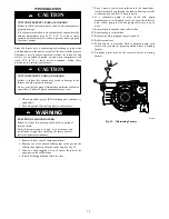
Fig. 27 - Gas Burner Assembly (Upflow)
GAS BURNER
HOT SURFACE
IGNITOR
GAS VALVE
MAIN LIMIT SWITCH
(BEHIND GAS VALVE)
FLAME
SENSOR
MANUAL RESET
LIMIT SWITCH
MANUAL RESET
LIMIT SWITCH
ASSEMBLY
A11320
Fig. 28 - Gas Burner Assembly (Downflow)
3. Inspect the combustion- air and vent PVC pipes for sags,
holes, cracks, water leaks, blockage or disconnections. Hori-
zontal portions of vent pipe must slope downward toward
the furnace.
4. If your furnace is free of the above conditions,turn on elec-
trical and gas supplies to the furnace.
5. Start your furnace and observe its operation. Watch the
burner flames to see if they are clear blue, almost transpar-
ent.. See Fig. 29. If you observe a suspected malfunction,
or the burner flames are not clear blue, call your dealer.
6. Replace main furnace door.
Burner Flame
Burner
Manifold
A11461
Fig. 29 - Burner Flame Adjustment


