
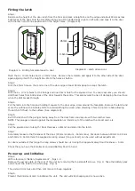

Step 10
Fit the battery pack into the unit. Replace the access plate and secure with the standoff screws.
Step 11
Fit the rubber escutcheons to front plate and the back plate. Present the front and rear lock assembly to the door,
locating the square drive in its recess and secure the two parts of the lock together with the fixing screws.
Step 12
Fit the two handles positioning the screw holes to the underside and secure with the grub screws provided.
Step 13
Check the operation of the lock by using the inside lever to check that the latch moves freely. If required, loosen
the fixing screws and adjust the position of the lock assemblies until the lever handle and latch are all moving
freely. Tighten the fixing screws.
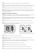
Step 14
To determine the vertical position of the plate - Close the door against the frame and mark the top and bottom of
the latch where it touches the frame. - Transfer these lines horizontally across the frame rebate.
Step 15
To determine the horizontal position of the plate - Measure the distance from the back edge of the door to the flat
face of the latch. (NOT the plunger.) Transfer this distance to the frame to show how far back the plate needs to
be to hold the door closed.
Step 16
Hold the strike plate in position on the frame so that its cut-out lines up with the three marks just made.
Step 17
Mark the positions of the fixing screws and draw around the cut-out in the strike plate. Chisel out an aperture to
about 15mm in depth to receive the latch bolt. (Diagram C)
Step 18
Fix the strike plate with one latch screw to the surface of the frame.
Step 19
FROM THE INSIDE: Gently close the door and check that the latch bolt enters the aperture easily with no
additional ‘play’ in the frame.
Slight adjustment can be made by moving the plate slightly. When satisfied, draw around the outline of the strike
plate, remove it and cut a rebate to enable the strike plate to lie flush with the surface.
Step 20
Fix the strike plate using two latch screws and check the operation of the door.
Step 21
Remove the strike plate and increase the aperture to accept the strike plate back box.
Step 22
Re-fix the strike plate and check the operation of the ‘anti-shim’ plunger and the door. (Diagram D)
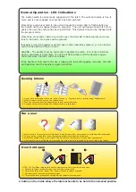
Step 23
The unit is now fully operational - See following pages for programming instructions and LED indications.
15mm
2.5mm
Diagram C - Strike plate and backbox
Diagram D - Strike plate position - Anti-shim plunger
Fitting the strike plate and backbox