22
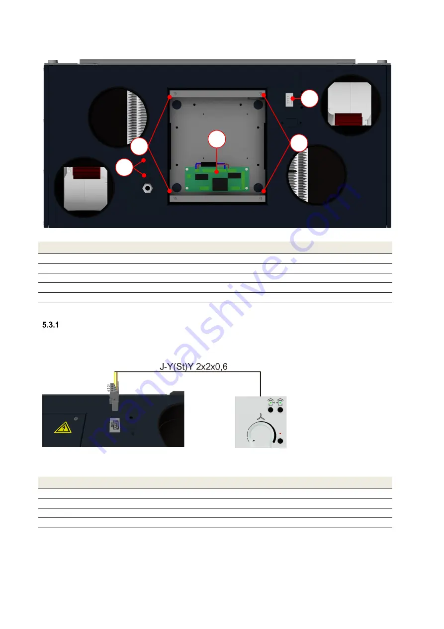
control board
A
. To do this, loosen the 4 screws
B
in the cover plate and connect the wires of the cable to the
relevant clamping points on the control board. This cable must be fed through an M16 cable gland and secured,
which is done by breaking out one of the pre-punched cable guides
D
Fig. 23: Casing side of electrical connections without control sheet cover plate
Item
Description
A
Control board
B
Control cover plate screws (4x)
C
Flat connector socket for control panel connecting cable
D
Pre-punched cable guides (2x) for M16 cable gland
FOCUS 200 Base terminal scheme
Table 4: Overview of the electrical connections
Connecting the control panel
5.3.1.1 Connecting the connecting cable to the flat connector plug
As shown in Fig. 24, a J-Y(St)Y 2x2x0.6 cable is recommended as the connecting cable between the control panel
and the FOCUS unit. The maximum permitted cable length is 25 m.
Fig. 24: Connecting cable with flat connector plug
The four wires are to be connected to the spring-type terminals of the flat connector as shown in Table 5.
Flat connector connecting cable wire
Signal
1
+12 V
2
U
s
(supply fan control voltage)
3
U
s
(extract air fan control voltage)
4
GND
Table 5: Flat connector wire assignment
5.3.1.2 Connecting the connecting cable to the control panel
The external control panel is installed in a standardised
∅
60 mm switchbox for in-wall installation.
The wires of the connecting cable are to be connected to the relevant connection terminal of the control panel
according to the flat connector wire assignment, as shown in Table 6.
C
B
B
A
D
Summary of Contents for FOCUS 200 Base
Page 1: ...Translation of the original instruction manual Heat Recovery Unit FOCUS 200 Base...
Page 30: ...30 Dimensions Fig 33 Dimensional drawing...
Page 31: ...31 FOCUS 200 Base terminal scheme Fig 34 Terminal assignment terminal plan...
Page 36: ...36 PDE Manual_Focus 200 Base_V1 1 V1122 DE Subject to change...


