background image

Installing the SmartNode device

32

SmartNode 5541 & 4141 Series User Manual 

3


• SmartNode Installation

2.

The power connection is made via the barrel jack on the rear panel of the SmartNode. No configuration is 
necessary for the power supply.

Connect the female end (barrel plug) to the barrel jack on the rear of the SmartNode (see 

figure 2

 on 

page 15 for an SN5541 or 

figure 4

 on page 19 for an SN4141) and the power supply male connectors to 

an appropriate power outlet.

3.

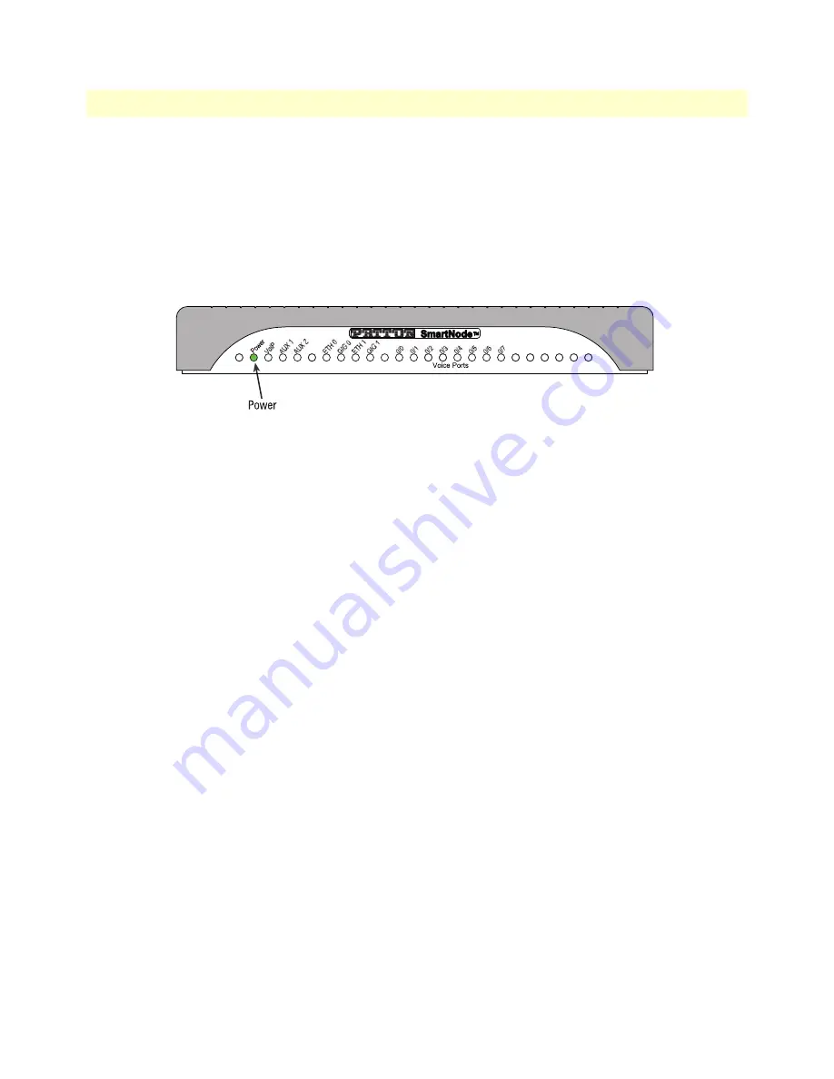
Verify that the green 

Power

 LED is lit (see 

figure 10

). It blinks fast during bootloader phase and blinks slow 

during boot process of Trinity Software. It becomes solid when the system is up and running.


.

Figure 10. Power LED

Congratulations, you have finished installing the SmartNode device! Now go to Chapter 4,

 “Initial Configura-

tion” 

on page 33.

Summary of Contents for SmartNode 5541 Series

Page 1: ...pport 1 301 975 1007 E mail support patton com WWW www patton com Part Number 07MDSN5541 SN4141 UM Rev A Revised November 30 2016 Important This is a Class A device and is intended for use in a light industrial environment It is not intended nor approved for use in an industrial or residential environment ...

Page 2: ...ms of such license Patton Electronics warrants all SmartNode router components to be free from defects and will at our option repair or replace the product should it fail within one year from the first date of the shipment This warranty is limited to defects in workmanship or materials and does not cover customer damage abuse or unauthorized modification If the product fails to perform as warrante...

Page 3: ...ions overview 23 3 SmartNode Installation 26 4 Initial Configuration 33 5 Contacting Patton for Assistance 40 A Compliance Information 43 B Specifications 45 C Cabling 49 D Port pin outs 52 E SmartNode Device Factory Configuration 55 F End User License Agreement 57 ...

Page 4: ...SmartNode 4141 Series VoIP Gateway 19 Port descriptions 20 Reset button behavior 20 Front panel LED definitions 21 2 Applications overview 23 Introduction 24 Application for SmartNode 5541 eSBC 24 Application for SmartNode 4141 VoIP Gateway 25 3 SmartNode Installation 26 Planning the Installation 27 Site log 27 Network information 27 Network Diagram 27 IP related information 27 Software tools 28 P...

Page 5: ...ess 38 Loading the Configuration optional 39 Additional Information 39 5 Contacting Patton for Assistance 40 Introduction 41 Contact information 41 Contacting Patton Technical Services for Free Support 41 Warranty Service and Returned Merchandise Authorizations RMAs 41 Warranty coverage 41 Out of warranty service 42 Returns for credit 42 Return for credit policy 42 RMA numbers 42 Shipping instruct...

Page 6: ...49 Introduction 50 Ethernet 50 Analog FXS 51 D Port pin outs 52 Introduction 53 Ethernet 53 FXS port 53 E SmartNode Device Factory Configuration 55 Introduction 56 F End User License Agreement 57 End User License Agreement 58 1 Definitions 58 2 Title 58 3 Term 58 4 Grant of License 58 5 Warranty 58 6 Termination 59 7 Other Licenses 59 ...

Page 7: ...net and FXS connectors SmartNode 5541 shown 30 9 Analog FXS connection 31 10 Power LED 32 11 Connecting the SmartNode device to your laptop PC 34 12 Connecting the SmartNode to the network 36 13 Connecting the SmartNode to a laptop PC 37 14 Connecting SmartNode device and PC to a LAN with DHCP server 37 15 Typical Ethernet straight through cable diagram for 10 100Base T 50 16 Typical Ethernet stra...

Page 8: ... panel ports 20 6 Power LED blink patterns 20 7 SmartNode 4141 LED Definitions 22 8 Sample site log entries 27 9 RJ 11 socket 31 10 Factory Default IP Address and Network Mask Configuration 35 11 Factory Default IP Address and Network Mask Configuration 38 12 10 100 Base T RJ 45 socket 53 13 1000Base T RJ 45 Socket 53 14 RJ 11 socket 53 ...

Page 9: ...ting Patton technical support for assistance Appendix A starting on page 43 provides compliance info for the SmartNode devices Appendix B starting on page 45 contains specifications for the routers Appendix C starting on page 49 provides cable recommendations Appendix D starting on page 52 describes the router s ports and pin outs Appendix E starting on page 55 describes how to obtain factory conf...

Page 10: ...power supply when the power cord is connected The mains outlet used to power the SmartNode device shall be within 10 feet 3 meters of the device be easily accessible and protected by a circuit breaker For AC powered units ensure that the power cable used meets all applicable stan dards for the country in which it is to be installed and that it is connected to a wall outlet which has earth ground F...

Page 11: ... soll Für mit Wechselstrom betriebene Geräte die 3 polige Netzstecker haben L1 L2 u GND oder Phase Neutralleiter u Schutzleiter muss die Steckdose geerdet sein Für mit Gleichstrom betriebene Geräte muss sichergestellt sein dass die Verbindung skabel für Spannung Strom erwartete Temperatur Entflammbarkeit und mecha nische Wartbarkeit geeignet sind WAN LAN u PSTN Ports Anschlüsse können unter gefähr...

Page 12: ... Meaning Garamond blue type Indicates a cross reference hyperlink that points to a figure graphic table or section heading Clicking on the hyperlink jumps you to the reference When you have finished reviewing the reference click on the Go to Previous View button in the Adobe Acrobat Reader toolbar to return to your starting point Helvetica bold type Commands and keywords are in boldface font Helve...

Page 13: ...SmartNode devices overview 14 SmartNode 5541 Series eSBC 15 Port descriptions 16 Reset button behavior 16 Front panel LED definitions 17 SmartNode 4141 Series VoIP Gateway 19 Port descriptions 20 Reset button behavior 20 Front panel LED definitions 21 ...

Page 14: ...41 and 4141 The SmartNode 5541 eSBC and 4141 VoIP Gateway are equipped with 2 4 or 8 FXS interfaces and provide the following major functions Analog telephony to voice over IP SIP conversion for 2 4 or 8 analog phone ports FXS Fax T 38 and G711 bypass support Modem bypass support Optional PacketSmart One Ethernet port Stateful Firewall QoS In addition the eSBC supports Second Ethernet port USB por...

Page 15: ...SIP calls non transcoded By default there are 4 SIP to SIP calls enabled Additional calls can be enabled by loading SNSW 1B licenses additional charge Figure 2 Examples of SN5541 Series rear panels The following models each equipped with two 10 100 1000Base T Ethernet ports are available SN5541 2JS2V EUI 2 voice calls SN5541 2JS2VSP EUI 2 voice calls 1 SN5541 4JS4V EUI 4 voice calls SN5541 4JS4VSP...

Page 16: ... by trained SmartNode technicians Start with the unit powered off Press and hold the Reset button while applying power to the unit Release the Reset button when the Power LED starts blinking so the unit will enter bootloader mode Furthermore the Reset button may be used to perform a system software image switch as follows 1 Hold the Reset button during boot The power LED flashes quickly for 2 seco...

Page 17: ...ed on the selected pattern Figure 3 SmartNode SN5541 Series front panels Front panel LED definitions Figure 3 shows SmartNode 4141 LEDs the LED definitions are listed in table 4 on page 18 Table 3 Power LED blink patterns Pattern Action 1 blink pause Boot normally 2 blinks pause Switch to backup image then boot Boot normally if the device only has a single image 3 blinks pause Erase all configurat...

Page 18: ...d to the SmartNode device Off indicates the unit is not configured or registered or has no active directly routed VoIP connection AUX 1 AUX 2 Auxiliary LEDs for future use Voice Ports 0 0 to 0 7 number of ports depending on model When lit indicates FXS port is enabled Flashes when there are ongoing or ringing calls Off when no line or phone is connected or the port is shut down ETH 0 ETH 1 When li...

Page 19: ...rear panels The following models each equipped with one 10 100 1000Base T Ethernet port are available SN4141 2JS EUI 2 voice calls SN4141 4JS EUI 4 voice calls SN4141 8JS EUI 8 voice calls On the products the following model code conventions apply JS stands for FXS ports EUI stands for external universal input power supply Note For a complete listing of available models refer to the SmartNode VoIP...

Page 20: ...ows 1 Hold the Reset button during boot The power LED flashes quickly for 2 seconds during which time the Reset button must remain pressed The power LED will begin a blink pattern described in table 3 2 Pressing the Reset button will change the blink pattern 10 seconds after the last Reset button press an action will be performed based on the selected pattern Table 5 Rear panel ports Port Location...

Page 21: ...General information Figure 5 SmartNode 4141 Series front panels Front panel LED definitions Figure 5 shows SmartNode 4141 LEDs the LED definitions are listed in table 7 on page 22 Note If an error occurs all LEDs will flash for more than 5 seconds before the device reboots ...

Page 22: ...evice Off indicates the unit is not configured or registered or has no active directly routed VoIP connection AUX 1 AUX 2 Auxiliary LEDs for future use Voice Ports 0 0 to 0 7 number of ports depending on model When lit indicates FXS port is enabled Flashes when there are ongoing or ringing calls Off when no line or phone is connected or the port is shutdown ETH 0 When lit indicates the Ethernet co...

Page 23: ...23 Chapter 2 Applications overview Chapter contents Introduction 24 Application for SmartNode 5541 eSBC 24 Application for SmartNode 4141 VoIP Gateway 25 ...

Page 24: ... controller www patton com voip gateway Application for SmartNode 5541 eSBC The SmartNode 5541 eSBC equipped with 2 Ethernet ports acts as an Enterprise Session Border Control ler securing the LAN from the WAN and it connects up to 8 Analog devices integrating them in to an All IP environment see figure 6 The major functions of the SN5541 eSBC are Network topology hiding Fraud prevention Service d...

Page 25: ...ms PoS terminals etc into an All IP environment see figure 7 The major functions of the SmartNode 4141 VoIP Gateway are Network quality assessment and monitoring optional PacketSmart1 QoS packet tagging Number normalization and mapping Fallback and survivability call routing to alternate SIP provider IP PBX Fax modem PoS integration and VoIP conversion Legacy telephone to VoIP conversion Figure 7 ...

Page 26: ...Software tools 28 Power source 28 Installing the SmartNode device 28 Placing the SmartNode device 28 Connecting cables 29 Installing a grounding wire on the SmartNode device s ground lug 30 Installing an interface cable on the SmartNode device s FXS interface ports 31 Connecting the 10 100 1000Base T Ethernet LAN and WAN cables 31 Connecting the power supply 31 ...

Page 27: ...es should include information such as listed in table 8 Network information Network connection considerations that you should take into account for planning are described for several types of network interfaces in the following sections Network Diagram Draw a network overview diagram that displays all neighboring IP nodes connected elements and telephony components IP related information Before yo...

Page 28: ...e device installation consists of the following Placing the device at the desired installation location see section Placing the SmartNode device on page 28 Installing the grounding wire if your SmartNode device came equipped with a surge protector and install ing interface and power cables see section Connecting cables on page 29 When you finish installing the SmartNode device go to Chapter 4 Init...

Page 29: ...rotection have SP in their model code All SmartNode SP models provide a secondary protection against over voltage and over current conditions surges including lightning strikes and power cross For phone lines that go across buildings TNV 3 a SmartNode SP device which includes K 21 compliant surge protection is required For SmartNode models without surge protection only TNV 2 circuits are allowed t...

Page 30: ...de device s ground lug 1 Route the grounding wire from a building ground connection to the SmartNode device 2 Connect the grounding wire to the ground lug of the SmartNode device see figure 8 3 Verify that the resistance of the ground path is less than 0 5 ohms According to UL60950 IEC62368 a connection to earth ground using the ground lug at the rear of the units see figure 8 is required to prote...

Page 31: ...et ports Any of the two ports can be connected to a host or hub switch with a straight through wired cable 1 Connect to the subscriber port of the broadband access modem DSL cable WLL to ETH 0 0 2 Connect port ETH 0 1 to your LAN For details on the Ethernet port pinout and cables refer to Appendix C Cabling on page 49 and Appendix D Port pin outs on page 52 Connecting the power supply Do the follo...

Page 32: ...r of the SmartNode see figure 2 on page 15 for an SN5541 or figure 4 on page 19 for an SN4141 and the power supply male connectors to an appropriate power outlet 3 Verify that the green Power LED is lit see figure 10 It blinks fast during bootloader phase and blinks slow during boot process of Trinity Software It becomes solid when the system is up and running Figure 10 Power LED Congratulations y...

Page 33: ...dress 34 Factory default IP Settings 34 Login 35 Changing the WAN IP address 35 Connecting the SmartNode device to the network 36 Connecting the SN4141 to a laptop PC 36 Configure the Desired IP Address 38 Factory default IP Settings 38 Login 38 Changing the WAN IP address 38 Loading the Configuration optional 39 Additional Information 39 ...

Page 34: ...ode device is ready Note The SmartNode device is equipped with Auto MDX Ethernet ports so you can use straight through cables for host or hub switch connections see figure 11 Figure 11 Connecting the SmartNode device to your laptop PC The SmartNode device comes with a built in DHCP server to simplify configuration Therefore to automatically configure the PC for IP connectivity to the SmartNode dev...

Page 35: ...iguration mode 192 168 1 1 enable 192 168 1 1 configure 192 168 1 1 cfg Changing the WAN IP address Select the context IP mode to configure an IP interface 192 168 1 1 cfg context ip ROUTER 192 168 1 1 ctx ip ROUTER Now you can set your IP address and network mask for the interface ETH 0 0 WAN Within this example a network 172 16 1 0 24 address is assumed The IP address in this example is set to 1...

Page 36: ...r hub switch connections see figure 12 Figure 12 Connecting the SmartNode to the network You can check the connection with the ping command from the SmartNode to another host on the network 172 16 1 99 if ip WAN ping IP Address of the host Note If the WAN address is notset to DHCP to ping a device outside your local LAN you must first configure the default gateway For information on con figuring t...

Page 37: ... 1 The SmartNode device is connected to a laptop PC see figure 13 that is configured with a fixed IP in the same range as the SmartNode device s IP address for instance PC s IP address 192 168 1 10 mask 255 255 255 0 Figure 13 Connecting the SmartNode to a laptop PC 2 The SmartNode device is connected to a local area network LAN that has a DHCP server running which assigns an IP address to the Sma...

Page 38: ...signed by the DHCP server Accessing your SmartNode device via a Telnet session displays the login screen Type the factory default login admin and leave the password empty Press the Enter key after the password prompt login admin password Enter 192 168 1 1 After you have successfully logged in you are in the operator execution mode indicated by as command line prompt With the commands enable and co...

Page 39: ...ou are ready to do phone calls after the SmartNode has rebooted Optionally you may execute the Wizard that matches your application online and import the generated cfg config into the SmartNode device In addition to that the Knowledgebase provides configuration file templates that may fit your application Note If your application is unique and not covered by any of Patton s configura tion template...

Page 40: ...ontact information 41 Contacting Patton Technical Services for Free Support 41 Warranty Service and Returned Merchandise Authorizations RMAs 41 Warranty coverage 41 Out of warranty service 42 Returns for credit 42 Return for credit policy 42 RMA numbers 42 Shipping instructions 42 ...

Page 41: ...nty program Note If you purchased your equipment from a Patton Electronics reseller ask your reseller how you should proceed with warranty service It is often more con venient for you to work with your local reseller to obtain a replacement Patton services our products no matter how you acquired them Warranty coverage Our products are under warranty to be free from defects and we will at our optio...

Page 42: ...t will be issued upon receipt and inspection of the equipment 30 to 60 days We will add a 20 restocking charge crediting your account with 80 of the purchase price Over 60 days Products will be accepted for repairs only RMA numbers RMA numbers are required for all product returns You can obtain an RMA by doing one of the following Completing a request on the RMA Request page in the Support section...

Page 43: ...43 Appendix A Compliance Information Chapter contents Compliance 44 EMC 44 Safety 44 Radio and TV interference 44 CE Declaration of Conformity 44 Authorized European Representative 44 ...

Page 44: ...on reception which can be determined by disconnecting the unit the user is encouraged to try to correct the interference by one or more of the following measures moving the computing equipment away from the receiver re orienting the receiving antenna and or plugging the receiving equipment into a different AC outlet such that the computing equipment and receiver are on different branches CE Declar...

Page 45: ...apter contents DSP 46 Voice Connectivity 46 Data Connectivity 46 Voice Processing signalling dependent 46 Fax and modem support 47 Voice Signalling 47 Voice Routing session router 47 IP Services 48 Management 48 System 48 Physical 48 ...

Page 46: ...202 generation Long Reach FXS 10 km 3REN load Surge and over voltage protection K 21 compliant SP models only Data Connectivity Two 10 100 1000Base TX Ethernet ports SN5540 One 10 100 1000Base TX Ethernet port SN4140 All ports full duplex auto sensing auto MDX USB 2 0 host port for 3G 4G Cellular Model data links Voice Processing signalling dependent 2 4 or 8 full duplex channels with voice CODECS...

Page 47: ...alling SIPv2 and SIPv2 over TLS licensed feature on SN4141 Series SIP call transfer redirect Overlap or en bloc dialing DTMF in band out of band Configurable progress tones Voice Routing session router Local switching hairpinning Least cost routing Interface huntgroups Call Distribution groups Number blocking Call Routing Criteria Interface Calling called party number Time of day day of week date ...

Page 48: ...and relay server DynDNS Management Web based GUI Trinity WEB Wizard Industry standard CLI with remote Telnet and SSH access fully documented HTTP web management and firmware loading TFTP configuration firmware loading HTTPS configuration firmware provisioning SNMP v1 agent MIB II and private MIB Built in diagnostic tools trace debug Secure Auto provisioning System Dual Core CPU Broadcom BCM53012 o...

Page 49: ...49 Appendix C Cabling Chapter contents Introduction 50 Ethernet 50 Analog FXS 51 ...

Page 50: ...or crossover cable to a host hubs switches PCs or other devices Note Connecting both Ethernet ports to the same switch will only work if the switch has a separate ARP table for each connection Figure 15 Typical Ethernet straight through cable diagram for 10 100Base T Figure 16 Typical Ethernet straight through cable diagram for 1000Base T The interconnecting cables shall be acceptable for external...

Page 51: ... machines answering machines etc via cables terminated with RJ 11 connectors see section FXS port on page 53 for details on port pinouts Figure 17 Connecting an FXS device The Interconnecting cables shall be acceptable for external use and shall be rated for the proper application with respect to volt age current anticipated temperature flammability and mechanical serviceability CAUTION ...

Page 52: ...52 Appendix D Port pin outs Chapter contents Introduction 53 Ethernet 53 FXS port 53 ...

Page 53: ...d FXS port The FXS ports use an RJ 11 connector with 6 positions The middle two positions 3 and 4 are used according to table 14 and figure 18 on page 54 Note Pins not listed are not used Table 12 10 100 Base T RJ 45 socket Pin Signal 1 TX 2 TX 3 RX 6 RX Table 13 1000Base T RJ 45 Socket Pin Signal 1 TRD0 2 TRD0 3 TRD1 4 TRD1 5 TRD2 6 TRD2 7 TRD3 8 TRD3 Table 14 RJ 11 socket Pin Signal 3 Ring 4 Tip...

Page 54: ...FXS port 54 SmartNode 5541 4141 Series User Manual D Port pin outs Figure 18 RJ 11 pinout diagram ...

Page 55: ...55 Appendix E SmartNode Device Factory Configuration Chapter contents Introduction 56 ...

Page 56: ...ction Factory configuration settings for the SmartNode device can be obtained with the following command through the CLI login admin password Enter 192 168 1 1 show config shipping config See Chapter 4 Initial Configuration on page 33 for more details about IP address settings for initial configu ration ...

Page 57: ...57 Appendix F End User License Agreement Chapter contents End User License Agreement 58 1 Definitions 58 2 Title 58 3 Term 58 4 Grant of License 58 5 Warranty 58 6 Termination 59 7 Other Licenses 59 ...

Page 58: ...desig nated Equipment at a site owned or leases by the End User B The End User may copy licensed Program s as necessary for backup purposes only for use with the des ignated Equipment that was first purchased or used or its temporary or permanent replacement C The End User is prohibited from disassembling decompiling reverse engineering or otherwise attempt ing to discover or disclose the Program ...

Page 59: ...ronics Company may terminate this Agreement should End User violate any of the provi sions of section 4 Grant of License on page 58 C Upon termination for A or B above or the end of the Term End User is require to destroy all copies of the licensed Program s 7 Other Licenses The Program may be subject to licenses extended by third parties Accordingly Patton Electronics Company licenses the Program...

Reviews: