background image

SmartNode devices overview

14

SmartNode 5540 & 4140 Series User Manual 

1


• General information

SmartNode devices overview

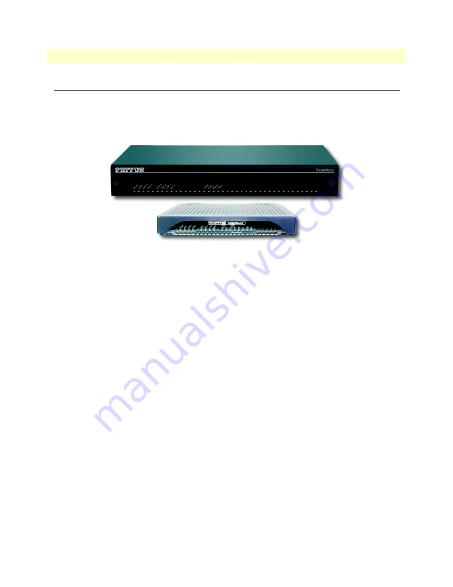
SmartNode SN5540 Enterprise Session Border Controllers (eSBCs) and Integrated Access Devices (IADs), and 
SN4140 VoIP Gateways (see 

figure 1

) combine IP routing, VoIP security, DSL access and quality of service 

(QoS) for up to 8 voice and FAX calls over any IP. Leverage low-cost IP services with packet-voice for complete 
branch office voice and data connectivity or for legacy equipment integration into All-IP environments.

Figure 1. SmartNode 5540 and 4140

The SmartNode SN5540 eSBC and IAD, and SN4140 VoIP Gateway are equipped with 2, 4 or 8 analog 
interfaces (FXS/FXO), and provide the following major functions:

Analog telephony to voice over IP (SIP) conversion for 2, 4 or 8 analog ports FXS/FXO

Fax T.38 and G711 bypass support

Modem bypass support

Optional PacketSmart

One Ethernet port

Stateful Firewall

QoS 

The 2-Ethernet-port gateways support:

Two Ethernet ports (IP Routing requires license to enable)

USB port

In addition, the eSBC supports:

IP routing including GRE, BGP, VPN1

4 SIP to SIP calls (license upgradeable up to a total of 200)

SIP TLS/SRTP included

SIP Registrar included

While the IAD models support on top of the eSBC

WAN access termination (VDSL2, ADSL2/2+, SHDSL, Fiber SFP) 

Section 

“SmartNode 5540 Series eSBC/IAD”

 on page 15 provides more information on the device. Section 

“SmartNode SN4140 Series VoIP Gateway”

 on page 18 describes the SmartNode 4140 Series.

Summary of Contents for SmartNode 5540 Series

Page 1: ...ateway User Manual Sales Office 1 301 975 1000 Technical Support 1 301 975 1007 E mail support patton com WWW www patton com Part Number 07MDSN5540 SN4140 UM Rev E Revised June 13 2019 This is a Class...

Page 2: ...rms of such license Patton Electronics warrants all SmartNode router components to be free from defects and will at our option repair or replace the product should it fail within one year from the fir...

Page 3: ...3 3 SmartNode Installation 27 4 Initial Configuration 35 5 Contacting Patton for Assistance 42 A Compliance Information 45 B Specifications 47 C Cabling 54 D Port pin outs 58 E SmartNode Device Factor...

Page 4: ...initions 21 2 Applications overview 23 Introduction 24 Application for SmartNode 5540 eSBC 24 Application for SmartNode 4140 VoIP Gateway 25 3 SmartNode Installation 27 Planning the Installation 28 Si...

Page 5: ...he WAN IP address 40 Loading the Configuration optional 41 Additional Information 41 5 Contacting Patton for Assistance 42 Introduction 43 Contact information 43 Contacting Patton Technical Services f...

Page 6: ...Fiber Ports F models only 61 E SmartNode Device Factory Configuration 62 Introduction 63 F Reset Button Functions 64 Introduction 65 Resetting the SmartNode device when it is operating and the Power...

Page 7: ...Power LED 34 12 Connecting the SmartNode device to your laptop PC 36 13 Connecting the SmartNode to the network 38 14 Connecting the SmartNode to a laptop PC 39 15 Connecting SmartNode device and PC...

Page 8: ...ss and Network Mask Configuration 37 9 Factory Default IP Address and Network Mask Configuration 40 10 WAN Interface Specifications 51 11 10 100 Base T RJ 45 socket 59 12 1000Base T RJ 45 Socket 59 13...

Page 9: ...ssistance Appendix A starting on page 45 provides compliance info for the SmartNode devices Appendix B starting on page 47 contains specifications for the routers Appendix C starting on page 54 provid...

Page 10: ...ower supply when the power cord is connected The mains outlet used to power the SmartNode device shall be within 10 feet 3 meters of the device be easily accessible and protected by a circuit breaker...

Page 11: ...soll F r mit Wechselstrom betriebene Ger te die 3 polige Netzstecker haben L1 L2 u GND oder Phase Neutralleiter u Schutzleiter muss die Steckdose geerdet sein F r mit Gleichstrom betriebene Ger te mus...

Page 12: ...Meaning Garamond blue type Indicates a cross reference hyperlink that points to a figure graphic table or section heading Clicking on the hyperlink jumps you to the reference When you have finished re...

Page 13: ...ion Chapter contents SmartNode devices overview 14 SmartNode 5540 Series eSBC IAD 15 Port descriptions 16 Front panel LED definitions 17 SmartNode SN4140 Series VoIP Gateway 18 Port descriptions 20 Fr...

Page 14: ...with 2 4 or 8 analog interfaces FXS FXO and provide the following major functions Analog telephony to voice over IP SIP conversion for 2 4 or 8 analog ports FXS FXO Fax T 38 and G711 bypass support Mo...

Page 15: ...upport 2 up to 8 voice calls FXS FXO VoIP and versa depending on the model see figure 2 and up to 200 SIP to SIP calls non transcoded By default there are 4 SIP to SIP calls enabled Additional calls c...

Page 16: ...ub or switch Analog voice ports FXS 0 0 FXS 0 7 FXS RJ 11 6 position 4 wire connectors that connect the device with an analog terminal a telephone for example FXS on hook voltage is 48V for each FXS p...

Page 17: ...eral information Figure 3 SmartNode SN5540 Series front panels Front panel LED definitions Figure 3 shows SmartNode SN5540 LEDs the LED definitions are listed in table 3 on page 18 Note If an error oc...

Page 18: ...IP server or a SIP device has registered to the SmartNode device Off indicates the unit is not configured or registered or has no active directly routed VoIP connection AUX 1 On when connected to Patt...

Page 19: ...wing model code conventions apply JS stands for FXS ports JO stands for FXO ports EUI stands for external universal input power supply 2ETH stands 2 Ethernet ports on gateway models Note For a complet...

Page 20: ...ports FXS 0 0 FXS 0 7 FXS RJ 11 6 position 4 wire connectors that connect the SmartNode device with an analog terminal a telephone for example FXO port EuroPOTS support ETSI EG201 188 FXS on hook vol...

Page 21: ...ble 5 SmartNode 4140 LED Definitions LED Description Power When lit indicates power is applied Blinks fast during bootloader phase and blinks slow during the boot process Becomes solid when the system...

Page 22: ...blink frequency is 2 per second In Connected state blink frequency is 1 per second Ethernet ETH 0 ETH 1 When lit indicates the Ethernet connection has a link indication Flashes when data is received...

Page 23: ...23 Chapter 2 Applications overview Chapter contents Introduction 24 Application for SmartNode 5540 eSBC 24 Application for SmartNode 4140 VoIP Gateway 25...

Page 24: ...pplication for SmartNode 5540 eSBC The SmartNode 5540 eSBC IAD equipped with 2 Ethernet ports acts as an Enterprise Session Border Controller securing the LAN from the WAN and it connects up to 8 Anal...

Page 25: ...desired see figure 7 Additionally 2ETH models have 2 Ethernet ports which enable them to be upgraded to enterprise session border controllers eSBCs after purchasing a software license The major functi...

Page 26: ...SmartNode 5540 4140 Series User Manual 2 Applications overview Note Additional functions can be unlocked by loading software licenses such as an eSBC license bundle see the product page under Orderin...

Page 27: ...ce 29 Connecting cables 30 Installation cable requirements for the WAN interface SN5540 2G 4G AVA AVB F Models 30 Installing a grounding wire on the SmartNode device s ground lug 31 Installing an inte...

Page 28: ...s should include information such as listed in table 6 Network information Network connection considerations that you should take into account for planning are described for several types of network i...

Page 29: ...lation location see section Placing the SmartNode device on page 29 Installing the grounding wire if your SmartNode device came equipped with a surge protector and install ing interface and power cabl...

Page 30: ...ling an interface cable on the SmartNode device s FXS and FXO interface ports on page 32 3 Connect the 10 100 1000Base T Ethernet LAN and WAN see section Connecting the 10 100 1000Base T Ethernet LAN...

Page 31: ...tNode device s ground lug 1 Route the grounding wire from a building ground connection to the SmartNode device 2 Connect the grounding wire to the ground lug of the SmartNode device see figure 8 3 Ver...

Page 32: ...the back of the device Some Models have FXO ports as well with equal number of ports as for FXS The FXS interfaces are con nected to analog devices via cables see figure 9 terminated with RJ 11 conne...

Page 33: ...e SFP port For details on the G SHDSL port pinout refer to section G SHDSL EFM ATM port 2G and 4G mod els on page 60 For details on the VDSL and ADSL port pinout refer to section VDSL ADSL Port A and...

Page 34: ...tNode device 34 SmartNode 5540 4140 Series User Manual 3 SmartNode Installation Figure 11 Power LED Congratulations you have finished installing the SmartNode device Now go to Chapter 4 Initial Config...

Page 35: ...IP address 36 Factory default IP Settings 36 Login 37 Changing the WAN IP address 37 Connecting the SmartNode device to the network 38 Connecting the SN4140 to a laptop PC 38 Configure the Desired IP...

Page 36: ...ntly Now the SmartNode device is ready Note The SmartNode device is equipped with Auto MDX Ethernet ports so you can use straight through cables for host or hub switch connections see figure 12 Figure...

Page 37: ...configuration mode 192 168 1 1 enable 192 168 1 1 configure 192 168 1 1 cfg Changing the WAN IP address Select the context IP mode to configure an IP interface 192 168 1 1 cfg context ip ROUTER 192 1...

Page 38: ...13 Connecting the SmartNode to the network You can check the connection with the ping command from the SmartNode to another host on the network 172 16 1 99 if ip WAN ping IP Address of the host Note...

Page 39: ...1 The SmartNode device is connected to a laptop PC see figure 14 that is configured with a fixed IP in the same range as the SmartNode device s IP address for instance PC s IP address 192 168 1 10 mas...

Page 40: ...igned by the DHCP server Accessing your SmartNode device via a Telnet session displays the login screen Type the factory default login admin and leave the password empty Press the Enter key after the...

Page 41: ...u are ready to do phone calls after the SmartNode has rebooted Optionally you may execute the Wizard that matches your application online and import the generated cfg config into the SmartNode device...

Page 42: ...ntact information 43 Contacting Patton Technical Services for Free Support 43 Warranty Service and Returned Merchandise Authorizations RMAs 43 Warranty coverage 43 Out of warranty service 44 Returns f...

Page 43: ...ty program Note If you purchased your equipment from a Patton Electronics reseller ask your reseller how you should proceed with warranty service It is often more con venient for you to work with your...

Page 44: ...will be issued upon receipt and inspection of the equipment 30 to 60 days We will add a 20 restocking charge crediting your account with 80 of the purchase price Over 60 days Products will be accepte...

Page 45: ...45 Appendix A Compliance Information Chapter contents Compliance 46 EMC 46 Safety 46 Radio and TV Interference FCC Part 15 46 EC Declaration of Conformity 46 Authorized European Representative 46...

Page 46: ...the cables try to correct the interference by one or more of the following measures moving the computing equipment away from the receiver re orienting the receiving antenna and or plugging the receiv...

Page 47: ...SP 48 Voice Connectivity 48 Data Connectivity 48 Voice Processing signaling dependent 48 Fax and modem support 49 Voice Signaling 49 Voice Routing session router 49 IP Services 50 WAN Interface if app...

Page 48: ...eeding ring and onhook voltage Caller ID FSK and ITU V 23 Bell 202 generation Long Reach FXS 10 km 3REN load per FXS port Data Connectivity Two 10 100 1000Base TX Ethernet ports SN5540 SN4140 2ETH One...

Page 49: ...dec fallback for modem bypass T 38 Fax Relay Gr 3 Fax 9 6 k 14 4 K G 711 Fax Bypass incl Super G3 Fax Voice Signaling SIPv2 SIPv2 over IPv6 SIPv2 over TLS licensed feature on SN4140 SIP call transfer...

Page 50: ...s IPv4 IPv6 router Dual Stack Routing functionalities are optional on SN4140 Programmable static routes and policy routing BGP GRE RIP VRRP OpenVPN L2TP IPSec License at additional charge ICMP redirec...

Page 51: ...G SHDSL EFM 2G and 4G models Support ITU T G991 2 G 994 1 standards Support ITU T G 998 1 G bond TC PAM line modulation 16 32 64 128 CO or CPE Mode IEEE 802 3 2Base TL aka 802 3ah compliant Rate nego...

Page 52: ...provisioning TR 069 config file and software image provisioning System Dual Core CPU Broadcom BCM53012 operating at 1GHz Memory 256 Mbytes DRAM 128 Mbytes Flash Interworking Interoperability G SHDSL I...

Page 53: ...c enclosure 7 3W x 1 6H x 6 1D in 18 5W x 4 1H x 15 5D cm Metal enclosure 12 1W x 1 5H x 6 1D in 30 7W x 3 8H x 15 5D cm Weight Plastic enclosure 15 9 oz 450g Metal enclosure 25 6 oz 725 7 g Power Con...

Page 54: ...54 Appendix C Cabling Chapter contents Introduction 55 Ethernet 55 Analog FXS 56 Analog FXO 57...

Page 55: ...r crossover cable to a host hubs switches PCs or other devices Note Connecting both Ethernet ports to the same switch will only work if the switch has a separate ARP table for each connection Figure 1...

Page 56: ...machines answering machines etc via cables terminated with RJ 11 connectors see section FXS port on page 59 for details on port pinouts Figure 18 Connecting an FXS device The Interconnecting cables sh...

Page 57: ...Note The phone line socket connector type and pinout available from the public network vary from country to country Refer to technical information avail able from your local operator for additional ca...

Page 58: ...pendix D Port pin outs Chapter contents Introduction 59 Ethernet 59 FXS port 59 FXO port 60 VDSL ADSL Port A and AVA AVB models only 60 G SHDSL EFM ATM port 2G and 4G models 60 Fiber Ports F models on...

Page 59: ...FXS port The FXS ports use an RJ 11 connector with 6 positions The middle two positions 3 and 4 are used according to table 13 and figure 20 on page 60 Note Pins not listed are not used Table 11 10 1...

Page 60: ...iddle two positions 3 and 4 are used according to table 13 on page 59 Note Pins not listed are not used VDSL ADSL Port A and AVA AVB models only Note Pins not listed are not used G SHDSL EFM ATM port...

Page 61: ...ucts sfpmodules asp 7 Tip 3 8 Ring 3 DO NOT insert an RJ11 connector into an RJ45 socket An RJ11 connector which has 4 or 6 pins see figure 21 on page 61 can permanently damage the 8 pins in an RJ45 s...

Page 62: ...62 Appendix E SmartNode Device Factory Configuration Chapter contents Introduction 63...

Page 63: ...tion Factory configuration settings for the SmartNode device can be obtained with the following command through the CLI login admin password Enter 192 168 1 1 show config shipping config See Chapter 4...

Page 64: ...ons Chapter contents Introduction 65 Resetting the SmartNode device when it is operating and the Power LED is lit 66 Resetting the SmartNode device when it is initially powered off 67 Very exceptional...

Page 65: ...he startup config settings which is followed by a SmartNode device reboot as indicated by the slow blinking of all LEDs see section Resetting the SmartNode device when it is operating and the Power LE...

Page 66: ...gure 23 SN5540 Reset button Resetting the SmartNode device when it is operating and the Power LED is lit The Reset button has the following behaviors depending on how many seconds see figure 24 the bu...

Page 67: ...ice is still not working properly see section Very exceptional case minimal config recovery Very exceptional case minimal config recovery If after performing the procedure in section Resetting the Sma...

Page 68: ...Minimal configuration file cli version 4 00 telnet server shutdown ssh server no shutdown web server http shutdown web server https shutdown The following procedure is NOT standard and is NOT to be u...

Page 69: ...it is initially powered off 69 SmartNode 5540 4140 Series User Manual F Reset Button Functions context ip ROUTER interface LAN ipaddress LAN 192 168 200 10 24 ipaddress DHCP dhcp port ethernet 0 0 bi...

Page 70: ...ent Chapter contents End User License Agreement 71 1 Definitions 71 2 Title 71 3 Term 71 4 Grant of License 71 5 Warranty 72 6 Termination 72 7 Notices 72 8 Other Licenses 72 9 Unenforceable Provision...

Page 71: ...software but are standard commercial software Except for the license use rights otherwise expressly provided in this Agreement no right title or interest in Patton Licensed Products is granted hereund...

Page 72: ...estroying all copies of the licensed Program s B Patton Electronics Company may terminate this Agreement should End User violate any of the provi sions of section 4 Grant of License on page 71 C Upon...

Page 73: ...reby irrevocably submits to the exclusive jurisdiction of the courts of the State of Maryland USA for any dispute arising under or relating to this agreement and waives user s right to institute legal...

Reviews: