


Introduction
3
SmartNode 4900 Quick Start Guide
Introduction
This Quick Start Guide leads you through the basic steps to set up a new SmartNode and to download a con-
figuration. Please note that this guide does not replace the detailed Software Configuration Guide and the Get-
ting Started Guide on the CD-ROM and available online at
SmartNodes can be used for a wide variety of IP and voice over IP applications. To support and ease the config-
uration of the SmartNodes configuration templates for the most important applications are available online at
http://www.patton.com/voip/appnotes.shtml
Setting up a new SmartNode consists of the following steps:
1.
Attach the power cable retainer clips to the unit
2.
Connect a PC to the SmartNode, log in and configure your LAN IP address (see
3.
Connect the SmartNode to the LAN (see
4.
Download a configuration example, adapt it to your network, and load it onto the SmartNode (see
)
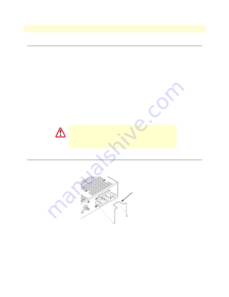
Attaching the cable retainer clips
To secure the power cord, it is necessary to attach the metal retainer clips (if applicable to your model). Squeeze
the clip and insert into the holes in the screws on either side of the power connector on your unit. The clip will
pop into place.
Figure 1. Attaching the cable retainer clips
Note
Refer to the
Getting Started Guide
on the CD-ROM or on the Patton
website for detailed instrauctions about grounding and connecting
power to your unit.
For FXO (/JO) models:
To maintain CE/EMC compliance,
attach the included snap-on ferrite clamp (Patton P/N 0818S-
02) to the 64/50 pin telco cable (not included but available
upon request) about four inches away from the FXO box telco
port connector.
IMPORTANT
Power cable
retainer clip
VoIPon www.voipon.co.uk [email protected] Tel: +44 (0)1245 808195 Fax: +44 (0)1245 808299


