


LED Indicators
15
FiberPlex 1008E User Manual
2
• Hardware Description
Ethernet Ports
RJ-45 Ports (Auto MDI/MDIX)
: The RJ-45 ports are auto-sensing for 10Base-T, 100Base-TX or 1000Base-T
devices connections. Auto MDI/MDIX means that the switch can connect to another switch or workstation
without changing the straight-through or crossover cabling. See
on page 17 for straight-through and crossover cabling schematics.
Note
“+” and “-” signs represent the polarity of the wires that make up each
wire pair.
All ports on this industrial Ethernet switch support automatic MDI/MDI-X operation. Users can use straight-
through cables (see ) for all network connections to PCs, servers, other switches or hubs. With straight-through
cable, pins 1, 2, 3, and 6, at one end of the cable, are connected straight through to pins 1, 2, 3 and 6 at the
other end of the cable.
shows the 10ase-T, 100Base-TX, 1000Base-TX MDI and MDI-X port pinouts.
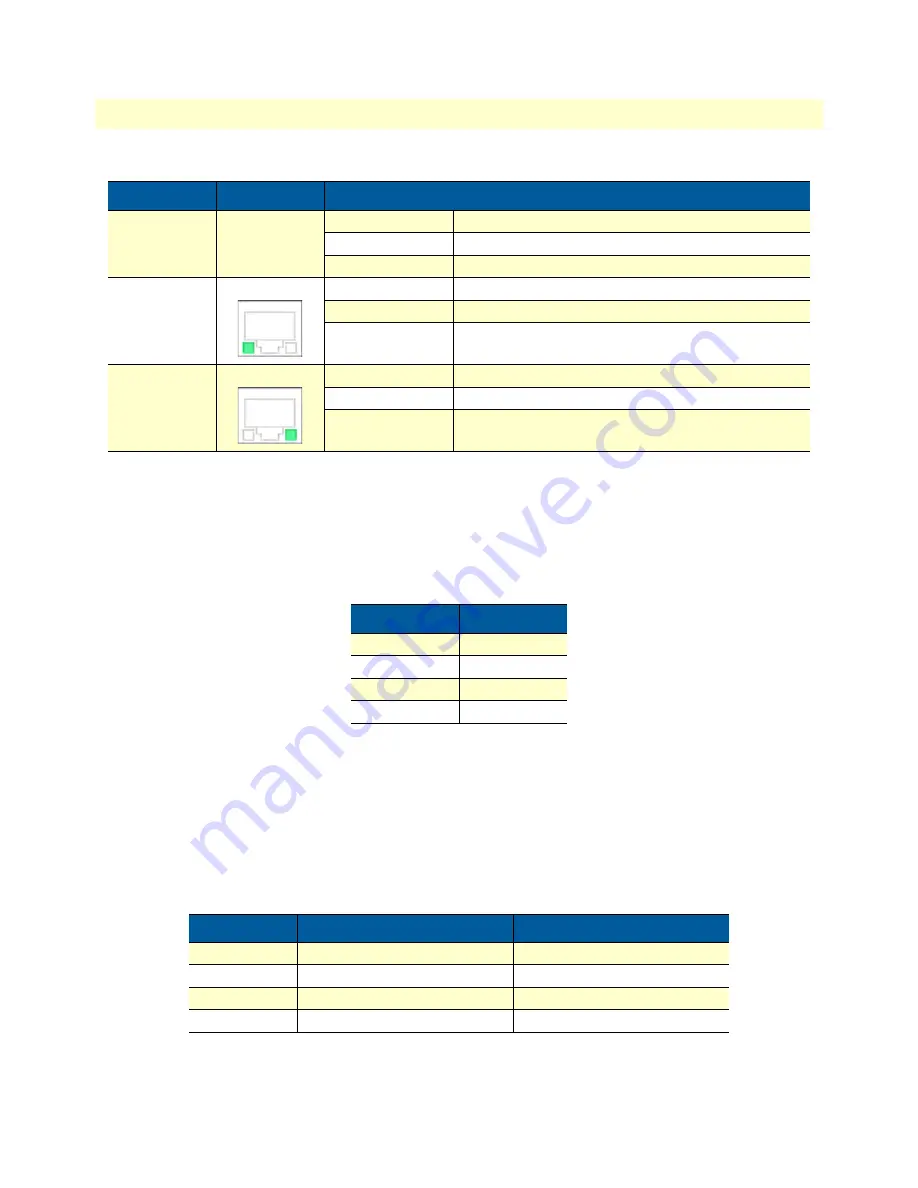
LNK/ACT
(SFP Port)
Green
On
Connected to network
Flashing
Networking is active
Off
Not connected to network
LAN Port 1–5
(Left LED)
Green
On
Connected to network, 1000 Mbps
Flashing
Networking is active
Off
Not connected to network
LAN Port 1–5
(Right LED)
Green
On
Connected to network, 100 Mbps/10 Mbps
Flashing
Networking is active
Off
Not connected to network
Table 2. RJ-45 pin assignments
Pin Number
Assignment
1
Rx+
2
Rx-
3
Tx+
6
Tx-
Table 3. Ethernet signal pinouts
Pin MDI-X
Signal Name
MDI Signal Name
1
Receive Data plus (RD+)
Transmit Data plus (TD+)
2
Receive Data minus (RD-)
Transmit Data minus (TD-)
3
Transmit Data plus (TD+)
Receive Data plus (RD+)
6
Transmit Data minus (TD-)
Receive Data minus (RD-)
Table 1. LED Indicators for FP1008E (Continued)
LED
Color
Description
Summary of Contents for FiberPlex 1008E
Page 11: ...11 Chapter 1 General information Chapter contents Overview 12 Features 12 Package Contents 12...
Page 22: ...22 Chapter 3 Mounting Installation Chapter contents DIN Rail Mounting 23 Wall Mounting 24...
Page 26: ...26 Chapter 4 Hardware Installation Chapter contents Installation Steps 27...
Page 28: ...28 Chapter 5 Network Application Chapter contents Introduction 29...
Page 30: ...30 Chapter 6 Troubleshooting Chapter contents Procedure 31...
Page 42: ...Physical 42 FiberPlex 1008E User Manual B Specifications Figure 22 FP1008E Physical Dimensions...
Page 43: ...43 Appendix C Accessories Chapter contents Optional Accessories 44...


