background image

Connecting a PC, logging in, and configuring the LAN IP address

5

SmartNode 4400 Quick Start Guide 

Connecting a PC, logging in, and configuring the LAN IP address

Connecting power and configuring the default IP address

Connect the SmartNode to the mains power supply using the included power supply and cable. When the 

RUN

 LED stops blinking and remains lit, the SmartNode is ready.

The factory default IP settings are listed in 

table 1

. If these addresses do not work with your network they must 

be changed. Contact your network administrator if you are not sure which IP address to use in 
your installation.

Note

The DHCP server is running on the ETH 0/1 of the SN4400 Series 
models. All Ethernet ports are pre-configured and active.

Connecting to a PC and logging in

1.

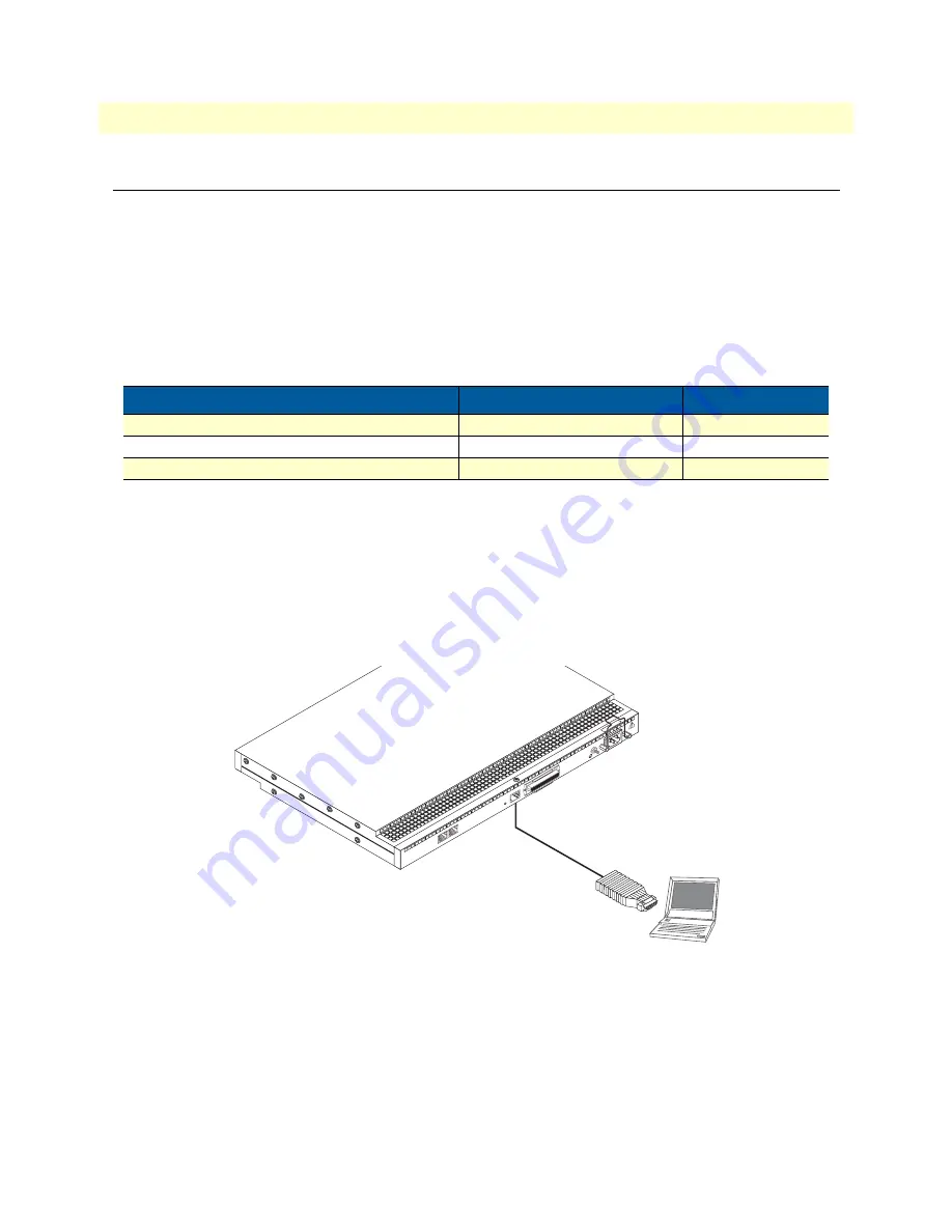
To access the SmartNode configuration, connect a PC equipped with an RS-232 console port to the 

Con-

sole

 port on the front of the SmartNode. Use the included black Ethernet cable and RJ45 to DB-9  adapter 

for this purpose (Model 16F-561).

Figure 2. Connecting to the PC

2.

Open a Terminal connection to the SmartNode. Use the Terminal program included with most PC operat-
ing systems (e.g. Hyper Terminal on Windows). 

Table 1. Factory default IP address and network mask configuration

Item

IP Addresss(es)

Network Mask

WAN interface Ethernet 0 (ETH 0/0)

DHCP

DHCP

LAN interface Ethernet 1 (ETH 0/1)

192.168.1.1

255.255.255.0

DHCP server address range

192.168.1.10-192.168.1.19

255.255.255.0

Console port

Laptop PC

Model 16F-561

adapter and cable

100-240V
(50-60 Hz)

1 AMP

UNIT EQ

UIPPED 

WITH DU

AL SUPPLIES

DISCONNECT BO

TH SUPPLIES

BEFORE SER

VICING

ETH 0/0

Console

Telco P

or

ts

50

Reset

ETH 0/1

Summary of Contents for SmartNode 07MSN4400-QS

Page 1: ...t patton com WWW www patton com Part Number 07MSN4400 QS Rev E Revised February 9 2012 Important This is a Class A device and is intended for use in a light industrial environment It is not intended n...

Page 2: ...re described in this document is furnished under a license and may be used or copied only in accordance with the terms of such license For information about the license go to www patton com Patton Ele...

Page 3: ...he interconnecting cables are rated for proper voltage current anticipated temperature flammability and mechanical serviceability WAN LAN PSTN ports connections may have hazardous voltages present reg...

Page 4: ...ge 5 for details 3 Connect the SmartNode to the LAN see page 7 4 Download a configuration example adapt it to your network and load it onto the SmartNode see page 8 Airflow requirements To ensure prop...

Page 5: ...g to a PC and logging in 1 To access the SmartNode configuration connect a PC equipped with an RS 232 console port to the Con sole port on the front of the SmartNode Use the included black Ethernet ca...

Page 6: ...e to configure an IP interface 172 16 40 1 cfg context ip router 172 16 40 1 ctx ip router 2 Set the IP address and network mask for the each IP interface eth0 for example Note For the examples in thi...

Page 7: ...ill need to configure the default gateway You may now start to configure the SmartNode from scratch using the CLI commands but we recommend that you start your configuration from a template See Downlo...

Page 8: ...Node device In this example we assume the TFTP server on the host with the IP address 172 16 1 11 and the configuration named SN cfg in the root directory of the TFTP server 172 16 1 99 if ip eth0 cop...

Page 9: ...ormity This equipment conforms to the requirements of Council Directive 1999 5 EC on the approximation of the laws of the member states relating to Radio and Telecommunication Terminal Equipment and t...

Page 10: ...NOTES 10 SmartNode 4400 Quick Start Guide NOTES...

Page 11: ...NOTES 11 SmartNode 4400 Quick Start Guide NOTES...

Page 12: ...NOTES 12 SmartNode 4400 Quick Start Guide NOTES...

Reviews: