


6
SmartNode 4950-NCE Series Quick Start Guide
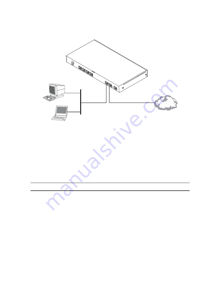
In general, the SmartNode will connect to the network via the
WAN (ETH 0/0)
port. This enables the SmartNode
to offer routing services to the PC hosts on
LAN (ETH 0/1)
port. The SmartNode 4950-NCE Series provides an
auto-MDX feature for both Ethernet ports, so you can use a straight-through or cross-over cable to connect to a
host or a switch (see
figure 2
).
Figure 2.
Connecting the SmartNode to the network
1.
You can check the connection with the ping command from the SmartNode to another host on the
local LAN.
172.16.1.99(if-ip)[WAN]#ping <IP Address of the host>
Note
If the WAN address is
not
set to DHCP, to ping a device outside your local LAN you must first configure
the default gateway. (For information on configuring the default gateway, refer to section “Set IP
addresses” in Appendix C, “Command Summary” of the
SmartNode Series SmartWare Software Config-
uration Guide
.)
5.0 Loading the configuration (optional)
Patton provides a collection of configuration templates on the support page at
www.patton.com/smart-
node
—one of which may be similar enough to your application that you can use it to speed up configuring the
SmartNode. Simply download the configuration note that matches your application to your PC. Adapt the config-
uration as described in the configuration note to your network (remember to modify the IP address) and copy
the modified configuration to a TFTP server. The SmartNode can now load its configuration from this server.
Note
If your application is unique and not covered by any of Patton’s configuration templates, you can man-
ually configure the SmartNode instead of loading a configuration file template. In that case, refer to the
SmartNode Series SmartWare Software Configuration Guide
for information on configuring the SmartNode
device.
Straight-through wired or crossover cable
LAN (ETH 0/1)
LAN
WAN (ETH 0/0)
Network
RS
-23
2
Co
nso
le
ET
H 0
/0
ET
H 0
/1
Reset
0/0
0/1
0/2
0/3
T1
/E
1