


12
11
5
5..0
0
IIN
NS
ST
TA
AL
LL
LA
AT
TIIO
ON
N
This section describes how to install the IM1/K and IM2RC/K mod-
ules into your mDSL modems. Please refer to the section in this manu-
al that describes your unit.
5.1 Installing the IM1/K
The
QuickConnect™ interface on the NetLink Modems are inter-
changeable Modules. Each
QuikConnect™ Module has a 50-pin card
edge connector on one side and a Network interface on the other.
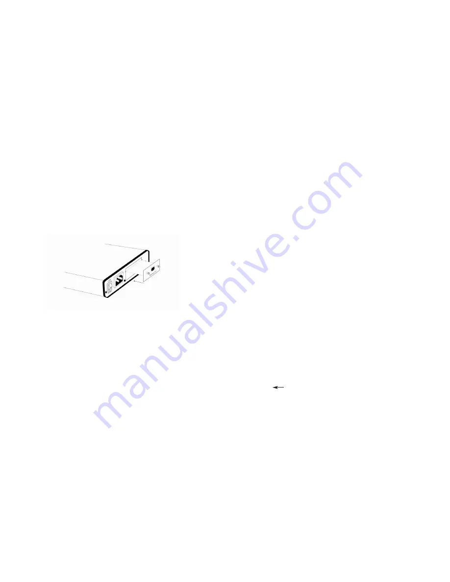
Figure 3 below shows how a
QuikConnect™ Module plugs into the
back of the Model 1095.
5.1.1 Changing
QuikConnect™ Modules
When you purchase a NetLink™ mDSL modem, it should be
shipped to you with the appropriate
QuikConnect™ Module already
installed. If you need to install a different
QuikConnect™ Module, fol-
low these steps:
Removing the Existing
QuikConnect™ Module
1) Turn the power switch off. Leave the power cord plugged into
a grounded outlet to keep the unit grounded.
2) Loosen the two thumbscrews on the module by turning them
counterclockwise.
3) Grasp the two thumbscrews and gently pull the module from
the unit. Apply equal force to the thumbscrews to keep the
module straight during the removal process
Installing the New
QuikConnect™ Module
1) Make sure the power switch is off. Leave the power cord
plugged into a grounded outlet to keep the unit grounded.
2) Hold the module with the faceplate toward you and align the
module with the guide slots in the rear panel of the NetLink
Chassis.
3) While keeping the module’s faceplate parallel with the NetLink
chassis rear panel, slide the module straight in – so that the
card edge contacts line up with the socket inside the chassis.
4) With the card edge contacts aligned with the socket, firmly seat
the module by using your thumbs to apply pressure directly to
the right and left edges of the module faceplate. Applying mod-
erate and
even pressure should be sufficient to seat the mod-
ule. You should hear it “click” into place.
5) To secure the module in place, push the thumbscrews into the
chassis and turn the screws clockwise to tighten.
5.2 Installing the IM2RC/K and Front Fuction Card
The Model IM2RC/K is a rear-mountable G.703/G.704 interface
card that works with the Patton Model 1095RC function card. The two
cards meet inside the rack chassis and plug into each other by way of
mating 50 pin card edge connectors. Use the following steps as a
guideline for installing each Model IM2RC/K and its function card mate
into the rack chassis:
1.
Slide the rear card into the back of the chassis along the
metal rails provided.
2.
Secure the rear card using the metal screws provided.
3.
Slide the front card into the front of the chassis. It should
meet the rear card when it’s almost all the way into the chas-
sis.
4.
Push the front card
gently into the card-edge receptacle of the
rear card. It should “click” into place.
5.
Secure the front card using the thumb screws.
The IM2RC/K is shipped with an IM1RC/K flip card. Ensure that
the flip card is secured in the flip card socket on the 1095RC with the
arrow (
) pointing toward the front panel. Please see the Model
1095RC User Manual (section 3.0 Configuration), for more informa-
tion on installing the flip card.
Figure 3. Installation of Model 1095 Plug-in K Module


