3.0 OPERATION
Data is transferred from the system to the tail using the system receive
clock, which is provided to the external clock input (terminal timing) of the tail
device. Data from the tail circuit is loaded into the 3004-MTE buffer using the
receive clock of the tail device. Data is transferred from the 3004-MTE buffer to
the system using the system transmit clock.
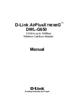
4.0 INSTALLATION
Connect the port of the 3004-MTE labeled "SYSTEM" to the main modem
or multiplexer sub-channel, i.e. the "system DCE".
Connect the port of the 3004-MTE labeled "TAIL" to the local tail-end DCE
or modem, i.e. the "tail-end DCE". The local tail-end modem must be set to
EXTERNAL CLOCK. (Local modem must accept TD data on the Terminal
Timing signal from the 3004-MTE.)
Note: The remote modem on the tail circuit must be configured for Receive
Recovered Clock (clock loopback).
BUFFER
TC
TT
TD
CD
RTS
RC
RD
TD
RC
RD
DSR
DTR
CTS
SG
FG
SG
FG
CD
CTS
DTR
RTS
DSR
TC
J1
SYSTEM
J2
TAIL
SYSTEM
DCE
TAIL
DCE
Set for
EXTERNAL CLOCK
TT
(XTC)
See Appendix for pin numbers and
connector signal assignments
Set for
EXTERNAL CLOCK
SYSTEM
3004-MTE
Local Modem
(External Clock)
Remote Modem
(Clock Loopback)
Terminal
(Remote DTE)
5
6